


1-301-30
1-301-30
1-30
Chapter 1: Product introductionChapter 1: Product introduction
Chapter 1: Product introductionChapter 1: Product introduction
Chapter 1: Product introduction
6.6.
6.6.
6.
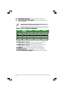
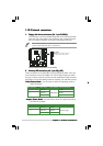
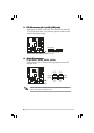
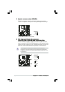
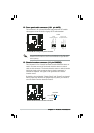
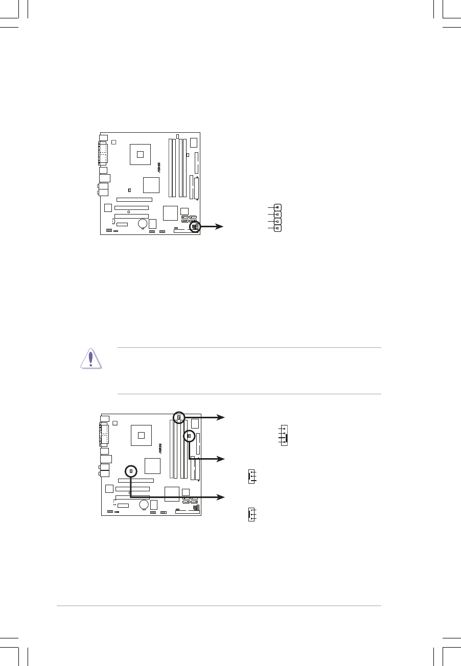
CPU, Power and Chassis fan connectorsCPU, Power and Chassis fan connectors
CPU, Power and Chassis fan connectorsCPU, Power and Chassis fan connectors
CPU, Power and Chassis fan connectors
(4-pin CPU_FAN, 3-pin PWR_RAN, 3-pin CHA_FAN)(4-pin CPU_FAN, 3-pin PWR_RAN, 3-pin CHA_FAN)
(4-pin CPU_FAN, 3-pin PWR_RAN, 3-pin CHA_FAN)(4-pin CPU_FAN, 3-pin PWR_RAN, 3-pin CHA_FAN)
(4-pin CPU_FAN, 3-pin PWR_RAN, 3-pin CHA_FAN)
The fan connectors support cooling fans of 350mA~740mA (8.88W
max.) or a total of 1A~2.22A (26.64W max.) at +12V. Connect the fan
cables to the fan connectors on the motherboard, making sure that the
black wire of each cable matches the ground pin of the connector.
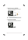
Do not forget to connect the fan cables to the fan connectors.
Insufficient air flow inside the system may damage the motherboard
components. These are not jumpers! DO NOT place jumper caps on the
fan connectors.
5.5.
5.5.
5.
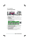
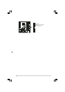
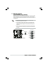
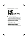
Speaker connector (4-pin SPEAKER)Speaker connector (4-pin SPEAKER)
Speaker connector (4-pin SPEAKER)Speaker connector (4-pin SPEAKER)
Speaker connector (4-pin SPEAKER)
This 4-pin connector is for the chassis-mounted system warning
speaker. The speaker allows you to hear system beeps and warnings.
®
P5LD2-VM DH
P5LD2-VM DH Speaker out connector
SPEAKER
+5V
1
GND
Speak Out
GND
®
P5LD2-VM DH
P5LD2-VM DH Fan connectors
PWR_FAN
GND
Rotation
+12V
CPU_FAN
GND
CPU FAN PWR
CPU FAN IN
CPU FAN PWM
CHA_FAN
GND
Rotation
+12V