


1-341-34
1-341-34
1-34
Chapter 1: Product introductionChapter 1: Product introduction
Chapter 1: Product introductionChapter 1: Product introduction
Chapter 1: Product introduction
13.13.
13.13.
13.
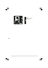
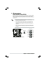
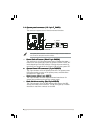
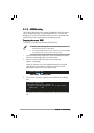
Chassis intrusion connector (4-1 pin CHASSIS)Chassis intrusion connector (4-1 pin CHASSIS)
Chassis intrusion connector (4-1 pin CHASSIS)Chassis intrusion connector (4-1 pin CHASSIS)
Chassis intrusion connector (4-1 pin CHASSIS)
This connector is for a chassis-mounted intrusion detection sensor or
switch. Connect one end of the chassis intrusion sensor or switch
cable to this connector. The chassis intrusion sensor or switch sends a
high-level signal to this connector when a chassis component is
removed or replaced. The signal is then generated as a chassis
intrusion event.
By default, the pins labeled “Chassis Signal” and “Ground” are shorted
with a jumper cap. Remove the jumper caps only when you intend to
use the chassis intrusion detection feature.
12.12.
12.12.
12.
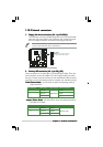
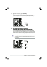
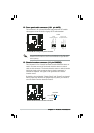
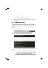
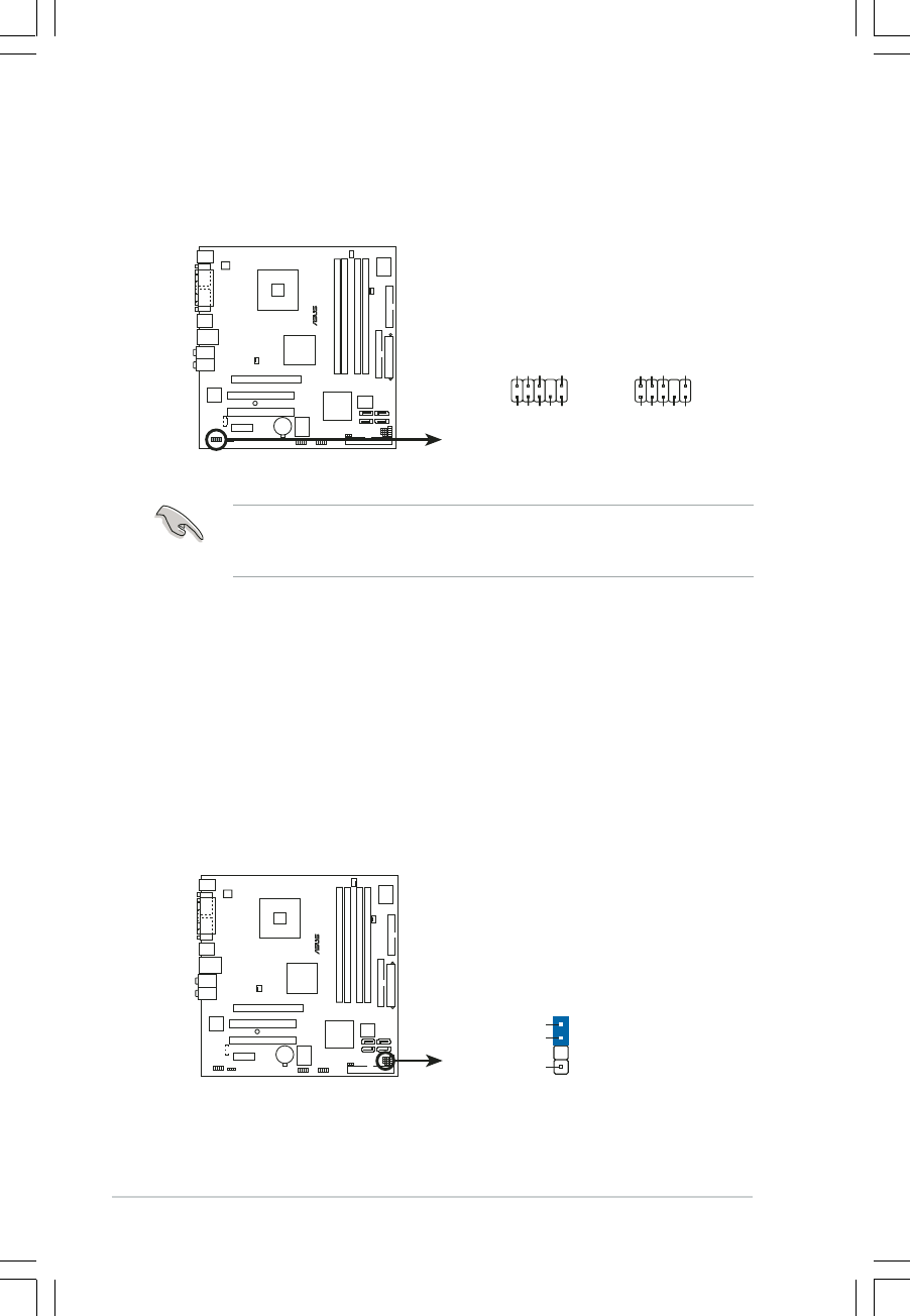
Front panel audio connector (10-1 pin AAFP)Front panel audio connector (10-1 pin AAFP)
Front panel audio connector (10-1 pin AAFP)Front panel audio connector (10-1 pin AAFP)
Front panel audio connector (10-1 pin AAFP)
This connector is for a chassis-mounted front panel audio I/O module
that supports either HD Audio or legacy AC’97 audio standard.
It is recommended that you connect a high-definition front panel audio
module to this connector to avail of the motherboard’s high-definition
audio capability.
®
P5LD2-VM DH
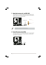
P5LD2-VM DH Analog front panel connector
AAFP
Legacy AC’97
compliant definition
Azalia
compliant definition
SENSE2_RETUR
PORT1 L
PORT2 R
PORT2 L
SENSE1_RETUR
SENSE_SEND
PORT1 R
PRESENCE#
GND
BLINE_OUT_L
MIC2
Line out_R
Line out_L
BLINE_OUT_R
NC
MICPWR
+5VA
AGND
®
P5LD2-VM DH
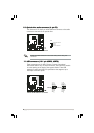
P5LD2-VM DH Chassis intrusion connector
CHASSIS
(Default)
+5VSB_MB
Chassis Signal
GND