


2-30 Chapter 2: Hardware information
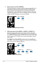
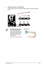
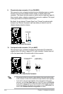
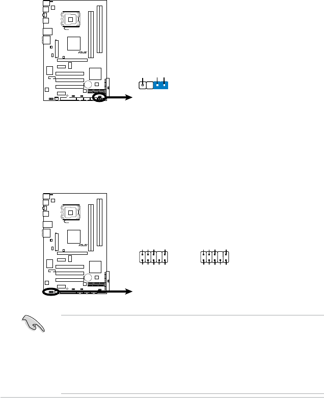
9. Chassis intrusion connector (4-1 pin CHASSIS)
This connector is for a chassis-mounted intrusion detection sensor or switch.
Connect one end of the chassis intrusion sensor or switch cable to this
connector. The chassis intrusion sensor or switch sends a high-level signal to
this connector when a chassis component is removed or replaced. The signal
is then generated as a chassis intrusion event.
By default, the pin labeled “Chassis Signal” and “Ground” are shorted with
a jumper cap. Remove the jumper caps only when you intend to use the
chassis intrusion detection feature.
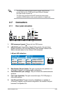
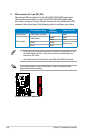
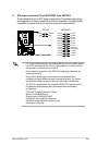
10. Front panel audio connector (10-1 pin AAFP)
This connector is for a chassis-mounted front panel audio I/O module that
supports either HD Audio or legacy AC`97 audio standard. Connect one end
of the front panel audio I/O module cable to this connector.
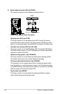
•
We recommend that you connect a high-denition front panel audio module
to this connector to avail of the motherboard’s high-denition audio capability.
•
If you want to connect a high-denition front panel audio module to this
connector, set the Front Panel Type item in the BIOS setup to [HD Audio];
if you want to connect an AC'97 front panel audio module to this connector,
set the item to [AC97]. By default, this connector is set to [HD Audio]. See
section 4.5.3 Onboard Devices Conguration for details.
P5QLD PRO
Intrusion Connector
CHASSIS
+5VSB_MB
Chassis Signal
GND
(Default)
P5QLD PRO
P5QLD PRO
P5QLD PRO
Front Panel Audio Connector
SENSE2_RETUR
PORT1L
PORT1R
PORT2R
SEBSE_SEND
PORT2L
SENSE1_RETUR
PRESENSE#
GND
AAFP
Legacy AC’97
compliant definition
NC
MIC2
Line out_R
Line out_L
NC
NC
MICPWR
NC
AGND
HD-audio-compliant
pin definition