


1-28 Chapter 1: Product introduction
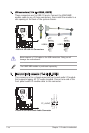
Never connect a 1394 cable to the USB connectors. Doing so will
damage the motherboard!
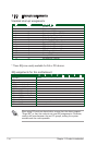
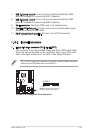
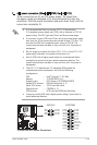
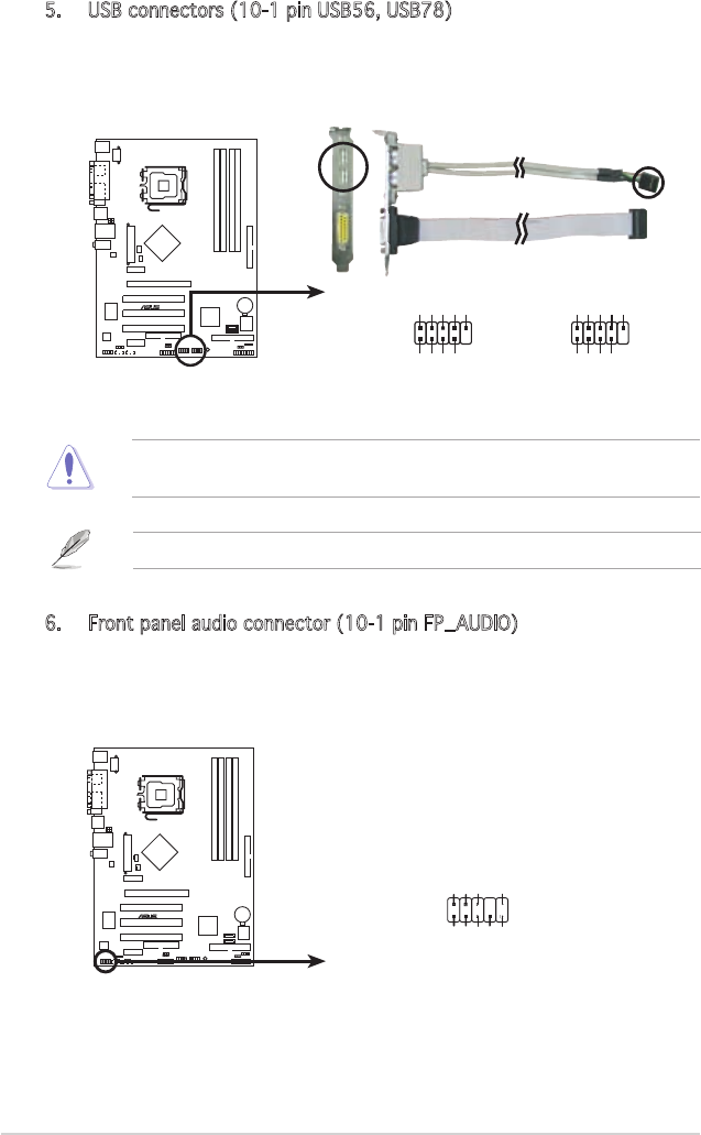
5. USB connectors (10-1 pin USB56, USB78)
These connectors are for USB 2.0 ports. Connect the USB/GAME
module cable to any of these connectors, then install the module to a
slot opening at the back of the system chassis.
The GAME/MIDI module is purchased separately.
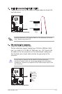
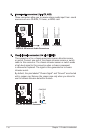
6. Front panel audio connector (10-1 pin FP_AUDIO)
This connector is for a chassis-mounted front panel audio I/O module
that supports legacy AC ʻ97 audio standard. Connect one end of the
front panel audio I/O module cable to this connector.
P5SD2-XSE
®
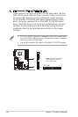
P5SD2-X SE USB 2.0 Connectors
USB56
USB+5V
USB_P6-
USB_P6+
GND
NC
USB+5V
USB_P5-
USB_P5+
GND
1
USB78
USB+5V
USB_P8-
USB_P8+
GND
NC
USB+5V
USB_P7-
USB_P7+
GND
1
P5SD2-X SE
®
P5SD2-X SE Front Panel Audio Connector
FP_AUDIO
BLINE_OUT_L
MIC2
Line out_R
Line out_L
BLINE_OUT_R
NC
MICPWR
+5VA
AGND