


ASUS P7P55-M 1-7
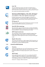
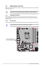
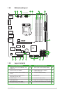
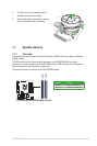
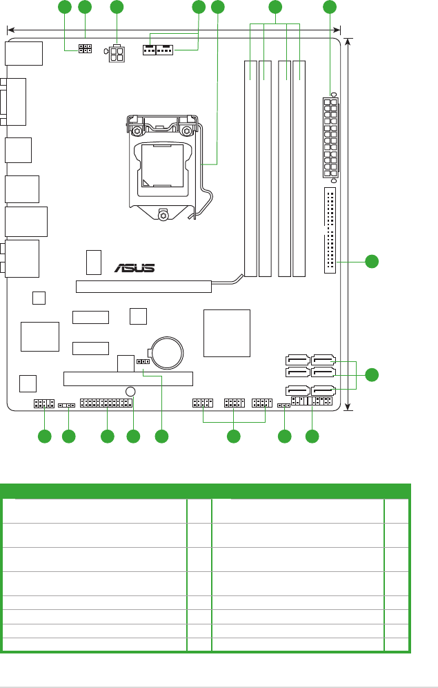
1.5.3 Motherboard layout
P7P55-M
PCIEX16
PCI1
PCIEX1_1
PCIEX1_2
LPT
USB1314 USB1112 USB910
USBPW9-14
AAFP
ATX12V
USBPW1-8
KBPWR
EATXPWR
CPU_FAN
CHA_FAN
Lithium Cell
CMOS Power
Super
I/O
AUDIO
ICS
9LRS954
VIA
VT1708
RTL
8112L
KB_USB78
16Mb
BIOS
JMB
381
SB_PWR
CLRTC
SPDIF_OUT
21.8cm(8.6in)
24.4cm(9.6in)
LGA1156
Intel
®
P55
DDR3 DIMM_A2 (64bit, 240-pin module)
DDR3 DIMM_A1 (64bit, 240-pin module)
DDR3 DIMM_B2 (64bit, 240-pin module)
DDR3 DIMM_B1 (64bit, 240-pin module)
LAN1_USB12
F_USB34
USB56
SATA1
SATA3
SATA5
SATA2
SATA4
SATA6
COM1
PRI_EIDE
PANEL
321 64 5 3
7
8
911012 1114 1315
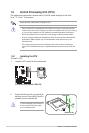
1.5.4 Layout contents
Connectors/Jumpers/Slots/LED Page Connectors/Jumpers/Slots/LED Page
1. USB device wake-up (3-pin USBPW1-8, 3-pin
USBPW9-14)
1-22 9. System panel connector (20-8 pin PANEL) 1-29
2. Keyboard power (3-pin KBPWR) 1-22 10. USB connectors (10-1 pin USB910,
USB1112, USB1314)
1-27
3. ATX power connectors (24-pin EATXPWR, 4-pin
ATX12V)
1-26 11. Clear RTC RAM (3-pin CLRTC) 1-21
4. CPU and chassis fan connectors (4-pin
CPU_FAN, 3-pin CHA_FAN)
1-27 12. Onboard LED 1-5
5. Intel CPU socket 1-8 13. LPT connector (26-1 pin LPT) 1-28
6. DDR3 DIMM sockets 1-13 14. Digital audio connector (4-1 pin SPDIF_OUT) 1-26
7. IDE connector (40-1 pin PRI_EIDE) 1-25 15. Front panel audio connector (10-1 pin AAFP) 1-24
8. Serial ATA connectors (7-pin SATA1-6) 1-28