


1-26 Chapter 1: Product introduction
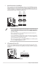
• For a fully congured system, we recommend that you use a power supply unit (PSU)
that complies with ATX 12 V Specication 2.0 (or later version) and provides a minimum
power of 400 W.
•
DO NOT forget to connect the 4-pin ATX +12V power plug. Otherwise, the system will
not boot up.
•
If you are uncertain about the minimum power supply requirement for your system,
refer to the Recommended Power Supply Wattage Calculator at http://support.asus.
com/PowerSupplyCalculator/PSCalculator.aspx?SLanguage=en-us for details.
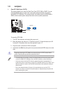
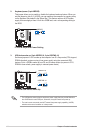
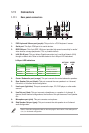
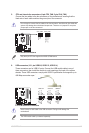
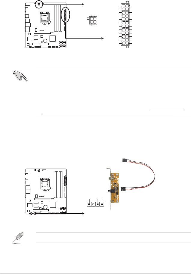
3. ATX power connectors (24-pin EATXPWR, 4-pin ATX12V)
These connectors are for ATX power supply plugs. The power supply plugs are
designed to t these connectors in only one orientation. Find the proper orientation and
push down rmly until the connectors completely t.
P7P55-M
P7P55-M ATX power connectors
EATXPWR
PIN 1
GND
+5 Volts
+5 Volts
+5 Volts
-5 Volts
GND
GND
GND
PSON#
GND
-12 Volts
+3 Volts
+3 Volts
+12 Volts
+12 Volts
+5V Standby
Power OK
GND
+5 Volts
GND
+5 Volts
GND
+3 Volts
+3 Volts
ATX12V
PIN 1
+12V DC
+12V DC
GND
GND
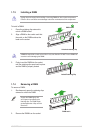
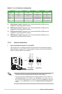
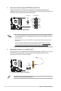
4. Digital audio connector (4-1 pin SPDIF_OUT)
This connector is for an additional Sony/Philips Digital Interface (S/PDIF) port. Connect
the S/PDIF Out module cable to this connector, then install the module to a slot
opening at the back of the system chassis.
The S/PDIF module is purchased separately.
P7P55-M
SPDIF_OUT
+5V
SPDIFOUT
GND
P7P55-M Digital audio connector