


1-24 Chapter 1: Product introduction
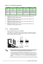
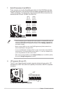
Audio 2, 4, 6, or 8-channel conguration
11. USB 2.0 ports 1 and 2. These two 4-pin Universal Serial Bus (USB) ports are
available for connecting USB 2.0 devices.
12. USB 2.0 ports 3 and 4. These two 4-pin Universal Serial Bus (USB) ports are
available for connecting USB 2.0 devices.
13. USB 2.0 ports 5 and 6. These two 4-pin Universal Serial Bus (USB) ports are
available for connecting USB 2.0 devices.
14. USB 2.0 ports 7 and 8. These two 4-pin Universal Serial Bus (USB) ports are
available for connecting USB 2.0 devices.
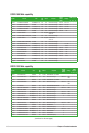
Port Headset 2-channel 4-channel 6-channel 8-channel
Light Blue Line In Line in Line in Line in
Lime Line Out Front Speaker Out Front Speaker Out Front Speaker Out
Pink Mic In Mic In Mic in Mic in
Orange - - Center/Subwoofer Center/Subwoofer
Black - Rear Speaker Out Rear Speaker Out Rear Speaker Out
Gray - - - Side Speaker Out
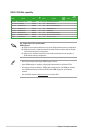
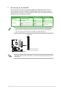
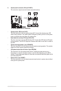
1.11.2 Internal connectors
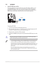
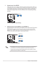
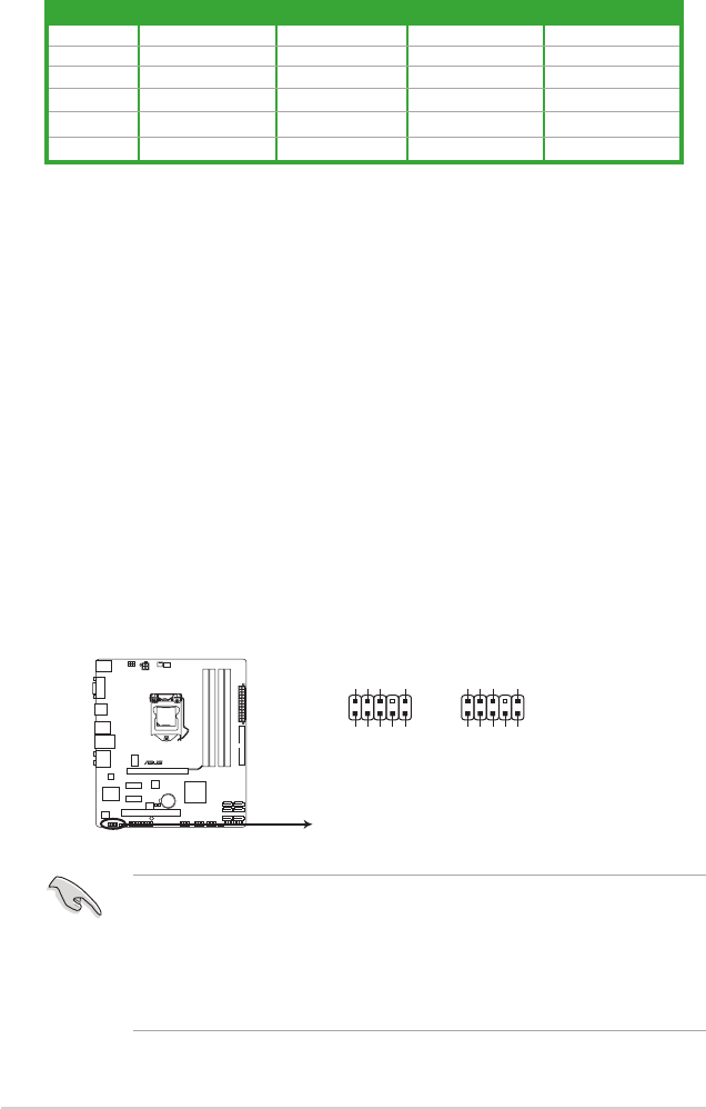
1. Front panel audio connector (10-1 pin AAFP)
This connector is for a chassis-mounted front panel audio I/O module that supports
either HD Audio or legacy AC`97 audio standard. Connect one end of the front panel
audio I/O module cable to this connector.
• We recommend that you connect a high-denition front panel audio module to this
connector to avail of the motherboard’s high-denition audio capability.
• If you want to connect a high-denition front panel audio module to this connector, set
the Front Panel Type item in the BIOS setup to [HD Audio]. If you want to connect an
AC'97 front panel audio module to this connector, set the item to [AC97]. By default, this
connector is set to [HD Audio]. See section 2.5.3 Onboard Devices Conguration for
details.
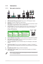
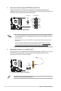
P7P55-M
P7P55-M Analog front panel connector
AAFP
PIN 1
GND
PRESENCE#
SENSE1_RETUR
SENSE2_RETUR
PORT1 L
PORT1 R
PORT2 R
SENSE_SEND
PORT2 L
HD-audio-compliant
pin definition
PIN 1
AGND
NC
NC
NC
MIC2
MICPWR
Line out_R
NC
Line out_L
Legacy AC’97
compliant definition