


ASUS P7P55-M 1-27
Do not forget to connect the fan cables to the fan connectors. Insufcient air ow inside the
system may damage the motherboard components. These are not jumpers! Do not place
jumper caps on the fan connectors!
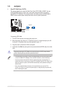
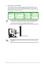
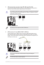
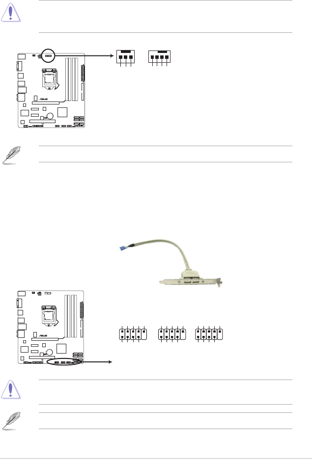
5. CPU and chassis fan connectors (4-pin CPU_FAN, 3-pin CHA_FAN)
Connect the fan cables to the fan connectors on the motherboard, ensuring that the
black wire of each cable matches the ground pin of the connector.
Only the 4-pin CPU fan supports the ASUS Q-FAN feature.
CPU_FAN
CPU FAN PWM
CPU FAN IN
CPU FAN PWR
GND
P7P55-M
P7P55-M fan connectors
Rotation
+12V
GND
CHA_FAN
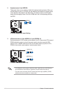
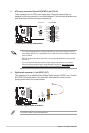
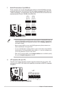
6. USB connectors (10-1 pin USB910, USB1112, USB1314)
These connectors are for USB 2.0 ports. Connect the USB module cable to any of
these connectors, then install the module to a slot opening at the back of the system
chassis. These USB connectors comply with USB 2.0 specication that supports up to
480 Mbps connection speed.
Never connect a 1394 cable to the USB connectors. Doing so will damage the
motherboard!
The USB module cable is purchased separately.
P7P55-M
P7P55-M USB2.0 connectors
PIN 1
USB+5V
USB_P10-
USB_P10+
GND
NC
USB+5V
USB_P9-
USB_P9+
GND
USB910
PIN 1
USB+5V
USB_P14-
USB_P14+
GND
NC
USB+5V
USB_P13-
USB_P13+
GND
USB1314
PIN 1
USB+5V
USB_P12-
USB_P12+
GND
NC
USB+5V
USB_P11-
USB_P11+
GND
USB1112