


Chapter 4: Motherboard information4-18
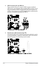
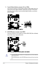
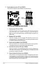
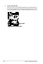
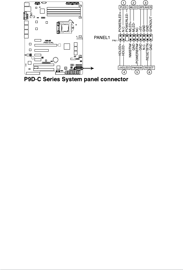
17. System panel connector (20-1 pin PANEL1)
This connector supports several chassis-mounted functions.
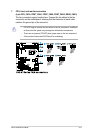
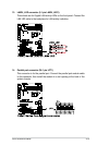
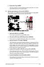
1. System power LED (3-pin PLED)
This 3-pin connector is for the system power LED. Connect the chassis
power LED cable to this connector. The system power LED lights up
when you turn on the system power, and blinks when the system is in
sleep mode.
2. Message LED (2-pin MLED)
This 2-pin connector is for the message LED cable that connects to the
front message LED. The message LED is controlled by Hardware monitor
to indicate an abnormal event occurance.
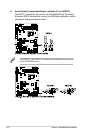
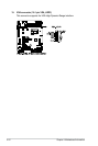
3. System warning speaker (4-pin SPEAKER)
This 4-pin connector is for the chassis-mounted system warning speaker.
The speaker allows you to hear system beeps and warnings.
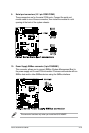
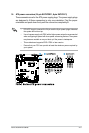
4. Hard disk drive activity LED (2-pin +HDLED)
This 2-pin connector is for the HDD Activity LED. Connect the HDD Activity
LED cable to this connector. The IDE LED lights up or ashes when data
is read from or written to the HDD.
5. Power button/soft-off button (2-pin PWRSW)
This connector is for the system power button. Pressing the power button
turns the system on or puts the system in sleep or soft-off mode depending
on the BIOS settings. Pressing the power switch for more than four seconds
while the system is ON turns the system OFF.