


ASUS RS300-E8 Series 4-19
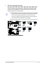
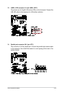
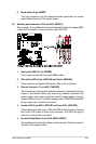
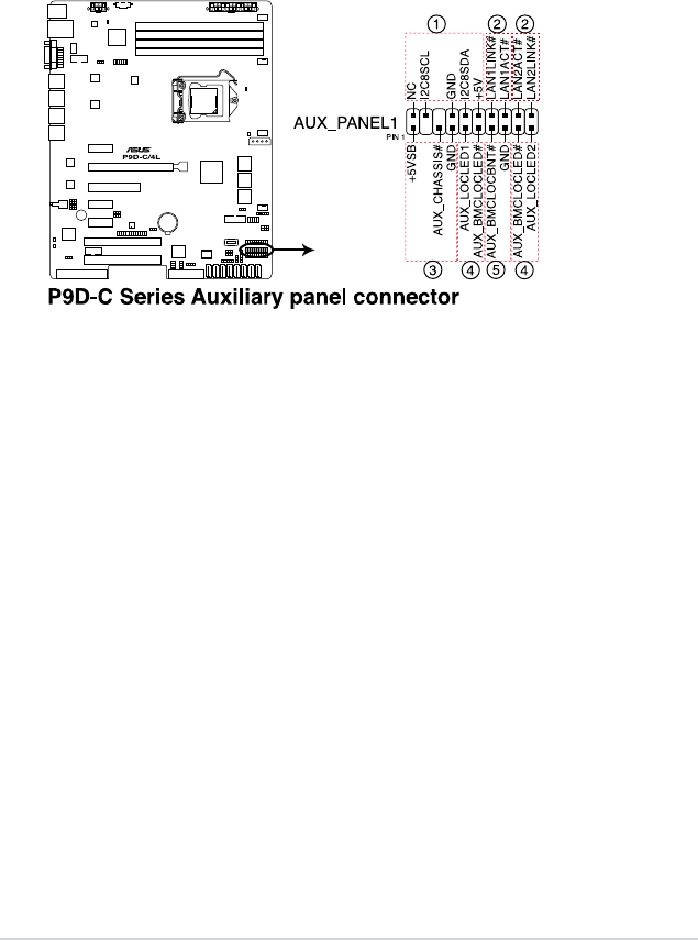
18. Auxiliary panel connector (20-2 pin AUX_PANEL1)
This connector is for additional front panel features including front panel SMB,
Locator LED and switch, chassis intrusion, and LAN LEDs.
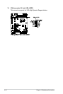
1. Front panel SMB (6-1 pin FPSMB)
These leads connect the front panel SMBus cable.
2. LAN activity LED (2-pin LAN1LINK and 2-pin LAN2LINK)
These leads are for Gigabit LAN activity LEDs on the front panel.
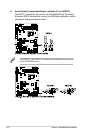
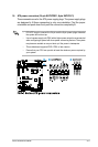
3. Chassis intrusion (4-1 pin AUX_CHASSIS)
These leads are for the intrusion detection feature for chassis with intrusion
sensor or microswitch. When you remove any chassis component, the
sensor triggers and sends a high-level signal to these leads to record a
chassis intrusion event. The default setting is short CASEOPEN and GND
pin by jumper cap to disable the function.
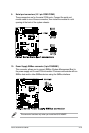
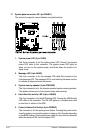
4. Locator LED (2-pin AUX_LOCLED1 and 2-pin AUX_LOCLED2)
These leads are for the Locator LED1 and LED2 on the front panel. Connect
the Locator LED cables to these 2-pin connector. The LEDs will light up
when the Locator button is pressed.
5. Locator Button/Switch (2-pin AUX_BMCLOCBNT)
These leads are for the locator button on the front panel. This button queries
the state of the system locator.
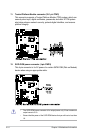
6. Reset button (2-pin RESET)
This 2-pin connector is for the chassis-mounted reset button for system
reboot without turning off the system power.