


4-44-4
4-44-4
4-4
Chapter 4: Motherboard infoChapter 4: Motherboard info
Chapter 4: Motherboard infoChapter 4: Motherboard info
Chapter 4: Motherboard info
2.2.
2.2.
2.
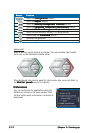
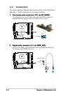
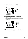
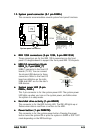
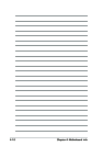
Digital audio connector (4-1 pin SPDIF_OUT)Digital audio connector (4-1 pin SPDIF_OUT)
Digital audio connector (4-1 pin SPDIF_OUT)Digital audio connector (4-1 pin SPDIF_OUT)
Digital audio connector (4-1 pin SPDIF_OUT)
(A) is for the SPDIF_OUT connector on the motherboard while (B) is
for the rear panel S/PDIF Out port.
A B
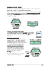
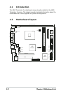
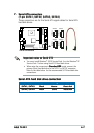
4.4 Connectors
This section describes and illustrates the connectors on the motherboard.
See page 1-7 for the description of rear panel connectors.
1.1.
1.1.
1.
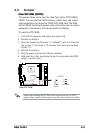
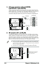
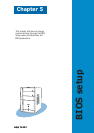
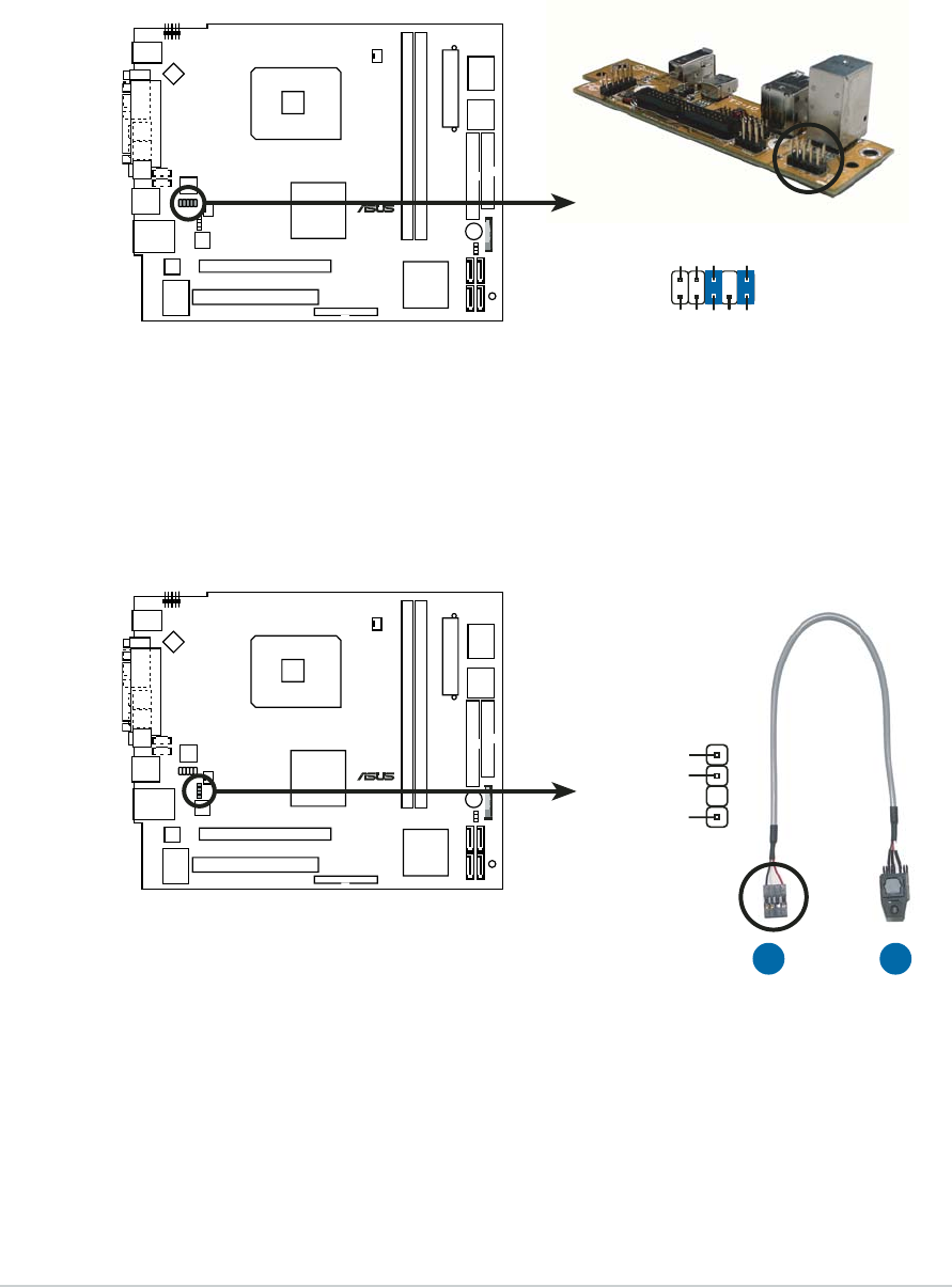
Front panel audio connector (10-1 pin FP_AUDIO)Front panel audio connector (10-1 pin FP_AUDIO)
Front panel audio connector (10-1 pin FP_AUDIO)Front panel audio connector (10-1 pin FP_AUDIO)
Front panel audio connector (10-1 pin FP_AUDIO)
This interface is for the FP_AUD connector on the front panel I/O
daughterboard to support the front panel audio I/O ports.
¤
Front panel audio connector
FP_AUDIO
BLINE_OUT_L
MIC2
Line out_R
Line out_L
BLINE_OUT_R
NC
MICPWR
+5VA
AGND
¤
Digital audio connector
+5V
SPDIFOUT
GND
SPDIF_OUT