


4-64-6
4-64-6
4-6
Chapter 4: Motherboard infoChapter 4: Motherboard info
Chapter 4: Motherboard infoChapter 4: Motherboard info
Chapter 4: Motherboard info
5.5.
5.5.
5.
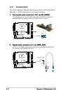
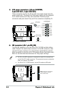
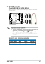
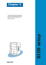
ATX power connectors (24-pin EATXPWR,ATX power connectors (24-pin EATXPWR,
ATX power connectors (24-pin EATXPWR,ATX power connectors (24-pin EATXPWR,
ATX power connectors (24-pin EATXPWR,
4-pin ATX12V1, 4-pin ATX12V2)4-pin ATX12V1, 4-pin ATX12V2)
4-pin ATX12V1, 4-pin ATX12V2)4-pin ATX12V1, 4-pin ATX12V2)
4-pin ATX12V1, 4-pin ATX12V2)
These connectors are for the 20-pin and 4-pin power plugs from the
power supply unit. The plugs from the power supply unit are designed
to fit these connectors in only one orientation. Find the proper
orientation and push down firmly until the connectors completely fit.
6.6.
6.6.
6.
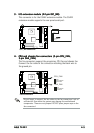
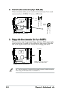
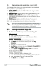
IDE connector (40-1 pin PRI_IDE)IDE connector (40-1 pin PRI_IDE)
IDE connector (40-1 pin PRI_IDE)IDE connector (40-1 pin PRI_IDE)
IDE connector (40-1 pin PRI_IDE)
The PRI_IDE connector is for the Ultra ATA/100 IDE hard disk ribbon
cable. Connect the cable’s blue connector to the IDE connector, then
connect the gray connector to a slave device (optical drive) and the
black connector to the Ultra ATA/100 master device (hard disk drive).
Refer to the hard disk documentation for the jumper settings.
•
Pin 20 on the IDE connector is removed to match the covered hole
on the UltraATA cable connector. This prevents incorrect orientation
when you connect the cables.
•
For Ultra ATA/133 IDE devices, use an 80-conductor IDE cable.
¤
ATX power connectors
ATX12V1
EATXPWR
+12V DCGND
+12V DCGND
+3 Volts
+3 Volts
Ground
+5 Volts
+5 Volts
Ground
Ground
Power OK
+5V Standby
+12 Volts
NC
+5 Volts
+3 Volts
-12 Volts
Ground
Ground
Ground
PSON#
Ground
+5 Volts
+12 Volts
+3 Volts
+5 Volts
1
Ground
+12V DC
Ground
+12V DC
Ground
ATX12V2
¤
IDE connector
NOTE: Orient the red markings
(usually zigzag) on the IDE
ribbon cable to PIN 1.
PIN 1
PRI_IDE