


ASUS TUSL2 User’s Manual 35
3. HARDWARE SETUP
Connectors
3. H/W SETUP
DMA Channels
3. H/W SETUP
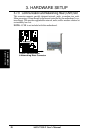
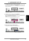
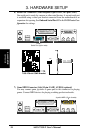
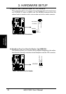
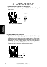
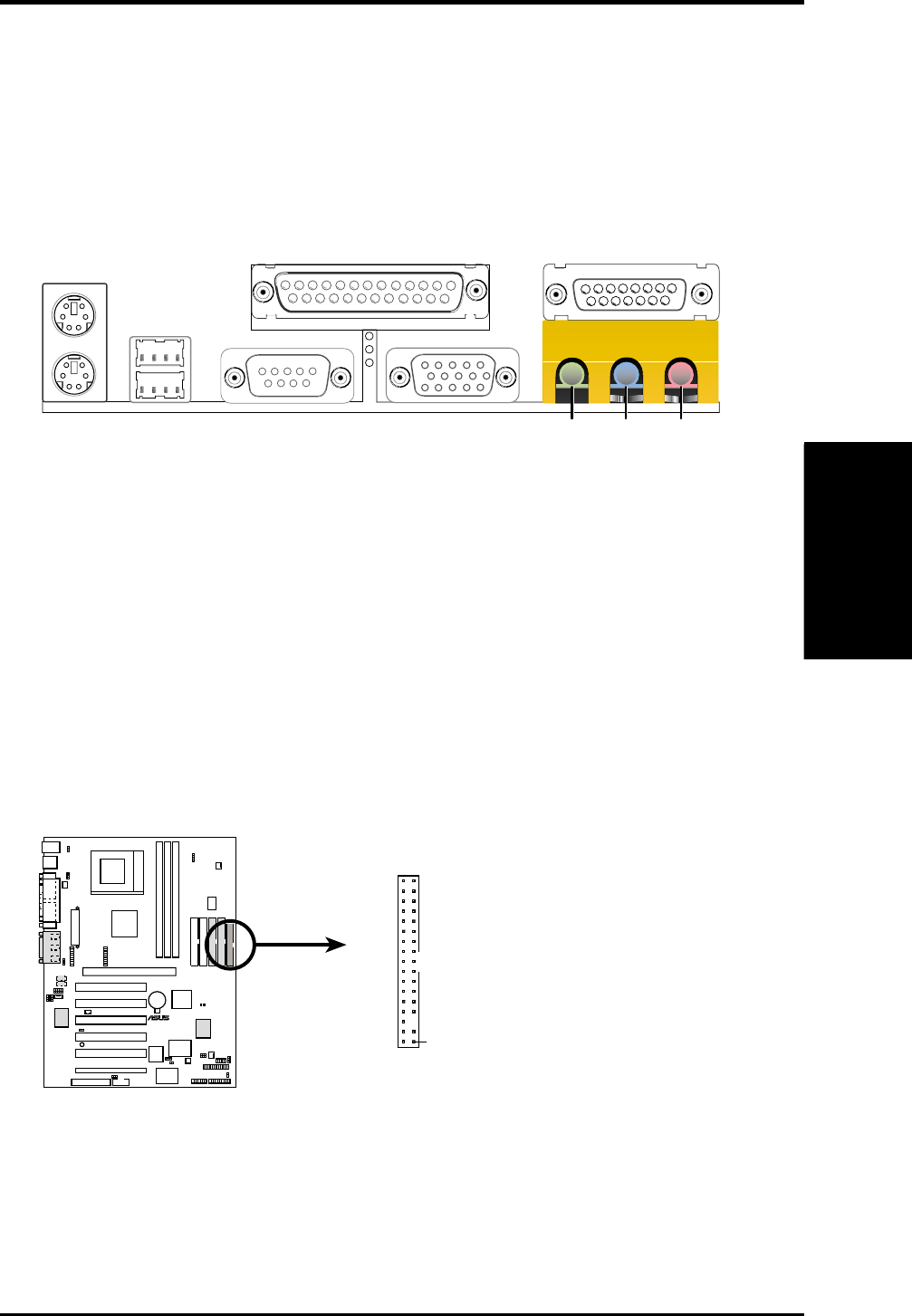
9) Floppy Disk Drive Connector (34-1pin FLOPPY)
This connector supports the provided floppy drive ribbon cable. After connect-
ing the single end to the board, connect the two plugs on the other end to the
floppy drives. (Pin 5 is removed to prevent inserting in the wrong orienta-
tion when using ribbon cables with pin 5 plugged).
TUSL2
®
COM1
NOTE: Orient the red markings on
the floppy ribbon cable to PIN 1.
TUSL2 Floppy Disk Drive Connector
PIN 1
FLOPPY
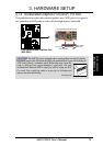
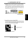
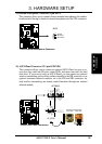
8) Audio Port Connectors (Three 1/8” Line_In, Line_Out, Mic) (optional)
Line Out (lime) can be connected to headphones or preferably powered speak-
ers. Line In (light blue) allows tape players or other audio sources to be re-
corded by your computer or played through the Line Out (lime). Mic (pink)
allows microphones to be connected for inputting voice. See Section 6.3 in
Software Reference, Multi-Channel Audio Feature Setup for information about
using Line Out, Line In and Mic for audio output.
MicLine InLine Out
1/8" Stereo Audio Connectors