


42 ASUS TUSL2 User’s Manual
Connectors
3. H/W SETUP
3. HARDWARE SETUP
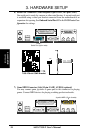
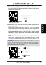
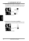
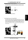
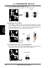
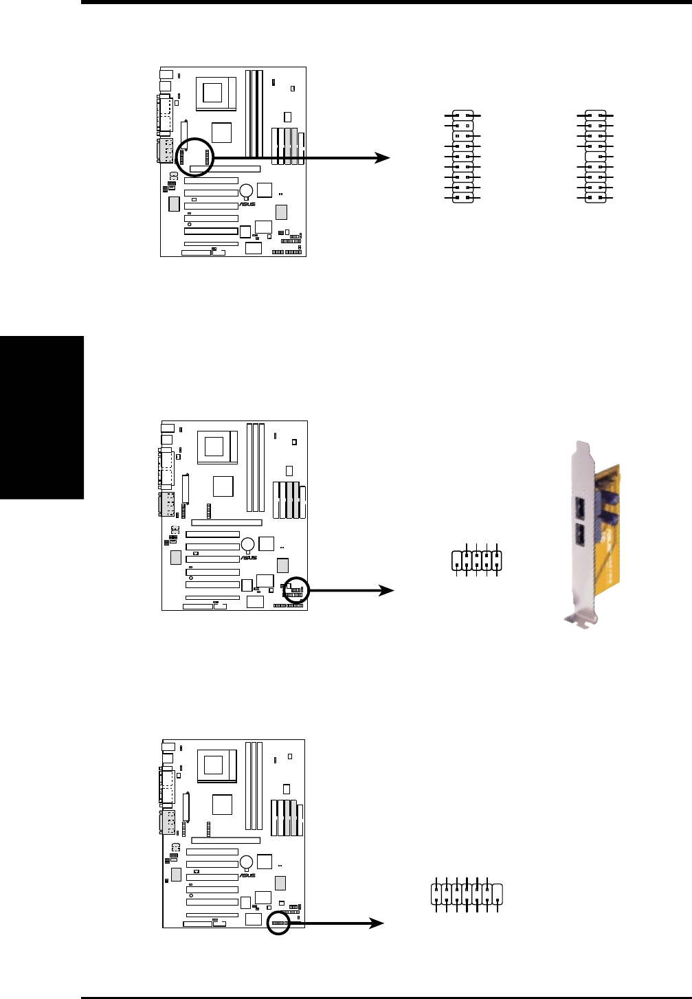
21) LCD-TV Headers (18-pin, 18-1 pin LCD TV)
These headers require optional modules for LCD or TV output.
TUSL2
®
COM1
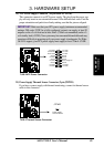
TUSL2 Front Panel USB Header
USB23
USB Power
USBP2–
USBP2+
GND
NC
USB Power
USBP3–
USBP3+
GND
15
610
TUSL2
®
COM1
TUSL2 LCD-TV Headers
LCDTV
1
LTVCL
+3V
ROMSEN
TVVSYNC
GND
DD4
DD3
DD1
GND
+1.8V
LTVDA
GND
BLANK
TVHSYNC
GND
DD2
DD0
+5V
GND
DD11
DD9
DD7
GND
DD5
CLKOUT1
+5V
PCIRST#
DD10
GND
DD8
DD6
CLKOUT0
GND
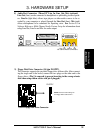
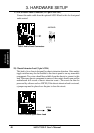
22) USB Header (10-1 pin USB23)
If the USB Ports on the back panels are inadequate,one USB header is available
for two additional USB ports. Connect the 10-pin ribbon cables from the pro-
vided 2-port USB connector set to the two midboard 10-pin USB headers and
mount the USB connector set to an open slot on your chassis.
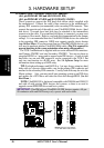
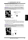
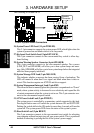
23) ASUS SmartCard Connector (10-1 pin SMARTCON)
This connector attaches to an optional SmartCard reader device. The SmartCard
reader accesses data on the memory chip of PC/SC SmartCards.
TUSL2
®
COM1
TUSL2 Smartcard
NC
SCRFET#
LED
RFU2
NC2
VCC
GND
SCRUI
SCRRES#
NC
SCRCLK
1
RFU1
SCRREST
SMARTCARD