


26 ASUS TX97-LE User’s Manual
III. INSTALLATION
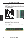
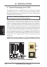
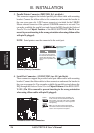
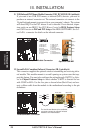
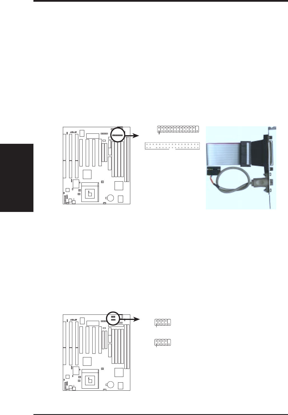
3. Parallel Printer Connector (PRINTER, 26-1 pin block)
This connector supports the included parallel port ribbon cable with mounting
bracket. Connect the ribbon cable to this connection and mount the bracket to
the case on an open slot. A PS/2 mouse connector is included for the USB/IR/
Mouse onboard connector if the optional USB/MIR connector is not used. You
can make available the parallel port and choose the IRQ through the Onboard
Parallel Port in Chipset Features of the BIOS SOFTWARE. (Pin 26 is re-
moved to prevent inserting in the wrong orientation when using ribbon cables
with pin 26 plugged).
NOTE: Serial printers must be connected to the serial port.
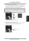
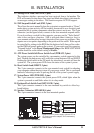
TIP: You may also remove
the bracket connectors and
mount them directly to the
case to save expansion slot
space.
Parallel
(
Printer
)
Connector
R
Pin 1
Connect the Red
stripe to Pin 1
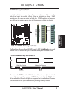
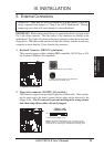
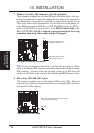
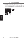
4. Serial Port Connectors (COM1/COM2, two 10-1 pin blocks)
These connectors support the provided serial port ribbon cables with mounting
bracket. Connect the ribbon cables to these connectors and mount the bracket to
the case on an open slot. You can make available the parallel port and choose the
IRQ through the Onboard Serial Port in Chipset Features of the BIOS SOFT-
WARE. (Pin 10 is removed to prevent inserting in the wrong orientation
when using ribbon cables with pin 10 plugged).
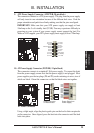
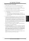
Onboard Serial Port Connectors
R
For these connectors to be available, you
must connect the included Serial cable set
from COM1 (using the 9-Pin male) & COM2
(using the 25-Pin male) to a free expansion
slot opening.
TIP: You may also remove the bracket
connectors and mount them directly to the
case to save expansion slot space.
COM 2
Pin 1
COM 1
Pin 1
(Connectors)
III. INSTALLATION