


ASUS TX97-LE User’s Manual 31
III. INSTALLATION
(Connectors)
III. INSTALLATION
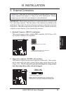
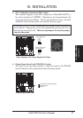
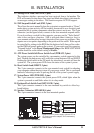
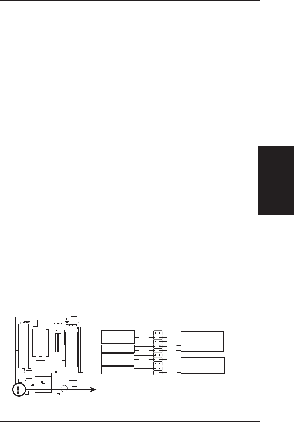
13. Message LED Lead (MSG.LED, 2 pins)
This indicates whether a message has been received from a fax/modem. The
LED will remain lit when there is no signal and blink when there is data transfer
or messages waiting in the inbox. This function requires ACPI OS support.
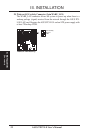
14. SMI Suspend Switch Lead (SMI, 2 pins)
This allows the user to manually place the system into a suspend mode or “Green”
mode where system activity will be instantly decreased to save electricity and
expand the life of certain components when the system is not in use. This 2-pin
connector (see the figure below) connects to the case-mounted suspend switch.
If you do not have a switch for the connector, you may use the “Turbo Switch”
since it does not have a function. SMI is activated when it detects a short to
open moment and therefore leaving it shorted will not cause any problems. May
require one or two pushes depending on the position of the switch. Wake-up can
be controlled by settings in the BIOS but the keyboard will always allow wake-
up (the SMI lead cannot wake-up the system). If you want to use this connector,
“Suspend Switch” in the Power Management Setup of the BIOS SOFTWARE
section should be on the default setting of Enable.
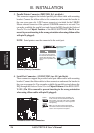
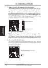
15. ATX Power Switch/Soft Power Switch Lead (PWR.SW, 2 pins)
The system power can be controlled by a momentary switch connected to this
lead. Pushing the button once will switch the system between ON and SLEEP.
Pushing the switch while in the ON mode for more than 4 seconds will turn the
system off. The system power LED shows the status of the system’s power.
16. Reset Switch Lead (RESET, 2 pins)
This 2-pin connector connects to the case-mounted reset switch for rebooting
your computer without having to turn off your power switch This is a preferred
method of rebooting in order to prolong the life of the system’s power supply.
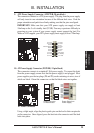
17. System Power LED (PWR.LED, 3 pins)
This 3-pin connector connects the system power LED, which lights when the
system is powered on and blinks when it is in sleep mode.
18. Keyboard Lock Switch Lead (KEYLOCK, 2 pins)
This 2-pin connector connects to the case-mounted key switch to allow key-
board locking.
19. Speaker Connector (SPEAKER, 4 pins)
This 4-pin connector connects to the case-mounted speaker.
R
System Panel Connectors
*
Requires an ATX power supply, optional ATX to
AT power connector adapter, and a momentary
switch button.
+5V
NC
GND
LOCK
GND
+5V
SPKR
Keyboard Lock
Speaker
Connector
Power LED &
GND
GND
+5V
GND
Reset SW
SMI Lead
Message
LED
GND
GND
GND
ATX Power
Switch*