


ASUS TX97-X User’s Manual 29
III. INSTALLATION
(Connectors)
III. INSTALLATION
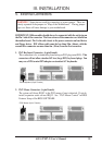
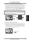
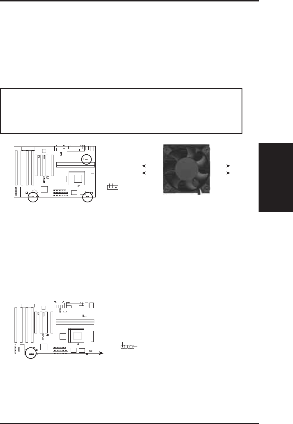
11. Chassis , CPU , & Power Supply Fan Connectors (3-pin FANPWR)
These connectors support cooling fans of 500mAMP (6WATT) or less. Orien-
tate the fans so that the heat sink fins allow airflow to go across the onboard heat
sink(s) instead of the expansion slots. Depending on the fan manufacturer, the
wiring and plug may be different. The red wire should be positive, while the
black should be ground. Connect the fan’s plug to the board taking into consid-
eration the polarity of the this connector. NOTE: The “Rotation” signal is to
be used only by a specially designed fan with rotation signal.
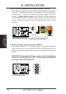
WARNING! The CPU and/or motherboard will overheat if there is no airflow
across the CPU and onboard heatsinks. Damage may occur to the motherboard
and/or the CPU fan if these pins are incorrectly used. These are not jumpers,
do not place jumper caps over these pins.
Orientate the fins so that air flow
runs across motherboard's regulators
Air Flow
Air Flow
12Volt Cooling Fan Power
Chassis Fan Power
CPU Fan Power
Power Supply Fan
GND
Rotation
+12V
R
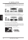
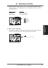
12. Chassis Open Alarm Lead (4-1pin CHASSIS)
This lead is for an open chassis monitor. A high level signal to the chassis signal
lead will indicate to the system that the chassis has been opened. For the chassis
open alarm feature to work, you must have the LM78 hardware monitor (op-
tional) onboard and connect a sensor or switch to the connector. The +5V power
comes from the power supply, when the A/C is connected.
Chassis Open Alarm Lead
Power supply standby +5V
Chassis Signal
Ground
R