


10 Audio Authority AVAtrix User Manual
Audio Authority AVAtrix User Manual 11
Installation
You may wish to consult with a qualied custom electronics installer if you are inexperienced with UTP cable
termination and wiring. You should be familiar with Cat 5e/6 cable termination tools, testing, and techniques.
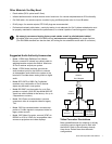
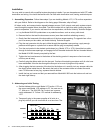
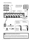
1. Assembling Expanders. Follow these steps if you are installing Models 1172, 1176 or other expanders
with your AVAtrix. Refer to the diagram on the facing page. Otherwise, skip to Step 3.
All video, audio, and communication signals between sources, Cat 5 outputs, and audio system outputs
travel through the special ribbon bus cable. The AVAtrix ships with a 4-port bus cable, leaving two open
ports for expanders. If you need to add more than two expanders, call Audio Authority Technical Support.
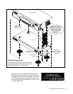
a. Lay the Model AVX-562 upside down on a protective surface, such as a terry cloth towel.
b. Remove the four feet and the bus access covers (save them and their attaching screws).
c. Gently feed the loose end of the bus cable out of the bus access opening. To upgrade from a four-
port to a seven-port bus cable, call Audio Authority Technical Support.
d. Plug the next connector into the port visible through the expander case opening—apply enough
pressure with ngers or a plastic tool to assure that the plug is completely seated.
e. Turn the next product to be stacked upside down (e.g. Model 1172 or 1176), thread the bus cable
through its bus access openings, and engage its four threaded studs with the four threaded holes in
the Model AVX-562 formerly occupied by the feet.
f. Tighten the hex head screws in the bottom of the stacking product in sequence a few turns each,
until they are all snug.
g. Carefully plug the ribbon cable into the bus port. Continue this stacking procedure until all units have
been assembled. View the bus through the bus port to be sure all plugs are fully seated.
h. After plugging the last connector of the bus into the bottom unit, carefully tuck any excess cable into
the empty space inside the unit. Be certain the back of the connector does not contact the metal
case. To disconnect a bus plug, squeeze the side latches.
i. Install the bus port cover and feet you removed from Model AVX-562 onto the bottom unit and turn
the stack right side up.
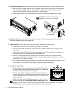
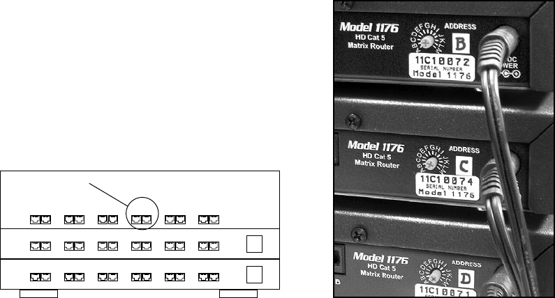
2. Addressing and Initial Testing.
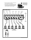
a. Set the Address dial on each Model 1172 and/or 1176: set
the upper-most Model 1176 address to “B”, the next one to
“C”, and so on. The AVX-562 Cat 5 output row is perma-
nently addressed “A”. Follow 1172 manual for addressing
1172.
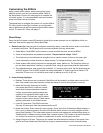
b. Temporarily plug in the power supplies of all units to a
plug strip so that you can turn them all on at one time. The
C
654321
B
(A)
654321
654321
AVX-562
1176
1176
Zone “A4”