


16 Audio Authority AVAtrix User Manual
Audio Authority AVAtrix User Manual 17
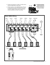
9879 Cat 5
receiver
Source 1
Source 2
Source 3
Source 1
Source 2
Source 3
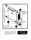
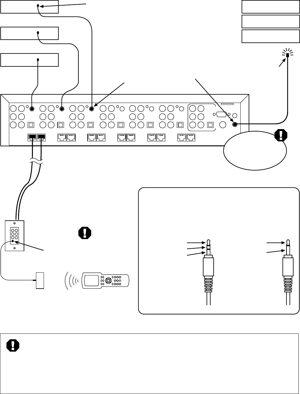
A single emitter or blaster may be
connected to the Main IR output
jack, or use the individual IR output
jacks at each source connection
for discrete source control.
Two-wire
IR blaster
or emitter
Connect IR receiver directly
to the wallplate/receiver - DO
NOT use a connecting block.
IR receiver
(12 volt, 3-wire
receivers only)
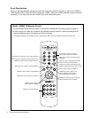
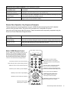
Remote Control
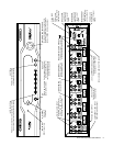
Main IR Output Jack
(3rd party IR from all zones)
Individual Source
Output Jacks
(IR Router)
Passive
IR Emitter
Receiver Pinout
Receivers are powered by
12 volts on the sleeve
contact of the Cat 5
wallplate/receiver IR jack.
Emitter Pinout
A passive emitter usually
has a two-conductor plug.
Tip = Signal
Ring = Ground
Sleeve = +12 Volts
Tip = Signal
Sleeve = Ground
Warning: Connect
receivers directly to
wallplate/receiver,
(12V, 3-wire only)
without a powered
connecting block.
Warning: Use only
non-powered emitters,
without connecting block.
AVX-562
Do not use a
powered connection
block or signal
amplifier with the
AVAtrix.
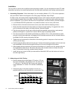
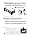
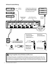
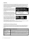
Infrared Control Wiring
Using Compatible Infrared Emitters and Receivers
The AVAtrix has an active, 12 volt IR pathway that allows it to power the IR receivers at the zones, and
drive emitters connected to the AVAtrix. Do not use powered IR systems that are designed to use a sepa-
rate power source, or equipment damage could result. The AVAtrix powers IR receivers with 12 volts; do
not use IR receivers designed for any other voltage. Use only three-wire receivers or damage could result.