14 BlendPRO-II • User’s Guide
NK==fåíêçÇìÅíáçå
Connectivity Diagram
`çååÉÅíáîáíó=aá~Öê~ã
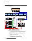
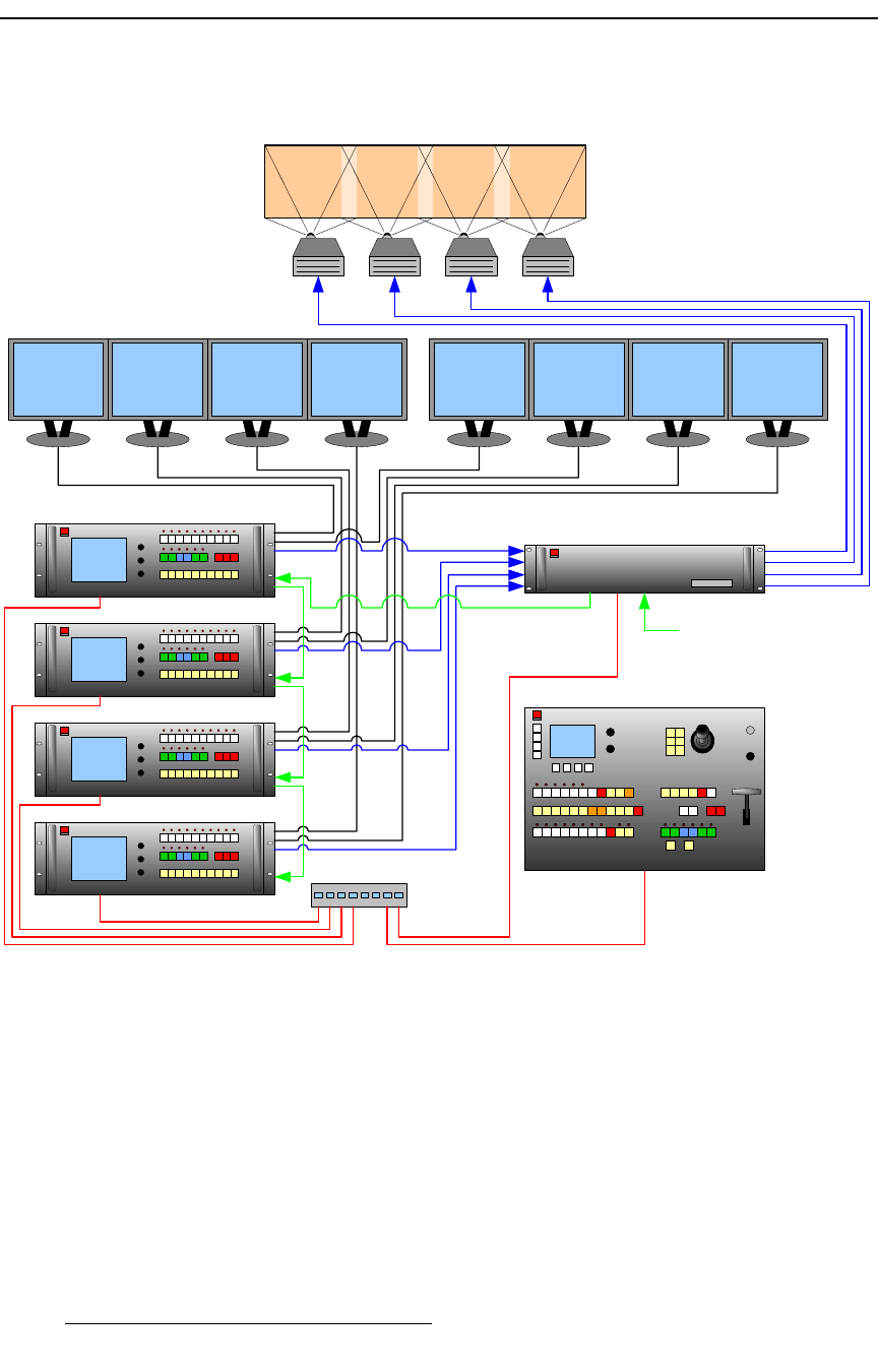
The figure below illustrates a sample connectivity diagram:
Figure 1-1. Typical BlendPRO-II Application (sample)
Please note the following points regarding the system:
• The maximum system configuration of four ScreenPRO-II units is shown.
• Ethernet connects the BlendPRO-II to all ScreenPRO-II units and the
ScreenPRO-II Controller, via a network switch.
• DVI signals connect the ScreenPRO-II outputs to BlendPRO-II, and the
BlendPRO-II to each projector input.
• Analog connectivity from each ScreenPRO-II is used for monitoring.
• The Widescreen Lock output from BlendPRO-II is used to lock each
ScreenPRO-II system. These connections are required.
ScreenPRO-II ID #1
ScreenPRO-II Controller
BlendPRO-II
Switch
X4 Widescreen Blend
Preview 1 Preview 2 Preview 3 Preview 4 Program 1 Program 2 Program 3 Program 4
ScreenPRO-II ID #2
ScreenPRO-II ID #3
ScreenPRO-II ID #4
Ethernet
DVI In
DVI Out or
Analog Out
Analog
Analog
Widescreen Lock
(Required)
Genlock In
(Optional)


