BlendPRO-II • User’s Guide 25
3. Installation
Signal Installation
páÖå~ä=fåëí~ää~íáçå
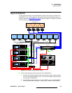
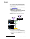
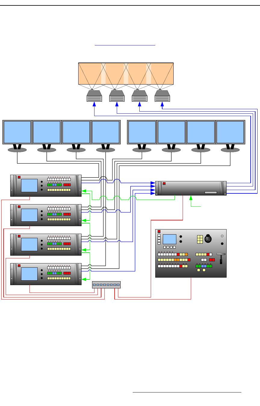
The figure below illustrates a sample BlendPRO-II system, which uses the maximum four
ScreenPRO-II units. Use this figure for reference during the signal installation process. If
required, refer to the “BlendPRO-II Rear Panel
” section on page 17 in Chapter 2 for details
on all rear panel connectors.
Figure 3-2. BlendPRO-II System Diagram (sample)
Use the following steps to install signals to/from the BlendPRO-II:
1. Connect your Program/Preview monitoring as required, using the analog outputs
from your selected ScreenPRO-II units. The units’ DVI outputs must be reserved
for connection to BlendPRO-II.
2. Connect Ethernet communications to all ScreenPRO-II units, to the BlendPRO-II,
and to the ScreenPRO-II Controller. A totally “local” network is recommended,
ScreenPRO-II ID #1
ScreenPRO-II Controller
BlendPRO-II
Switch
X4 Widescreen Blend
Preview 1 Preview 2 Preview 3 Preview 4 Program 1 Program 2 Program 3 Program 4
ScreenPRO-II ID #2
ScreenPRO-II ID #3
ScreenPRO-II ID #4
Ethernet
DVI In
DVI Out or
Analog Out
Analog
Analog
Widescreen Lock
(Required)
Genlock In
(Optional)


