BlendPRO-II • User’s Guide 19
2. Hardware Orientation
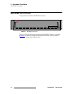
BlendPRO-II Rear Panel
6) Outputs Section
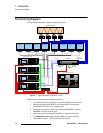
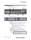
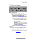
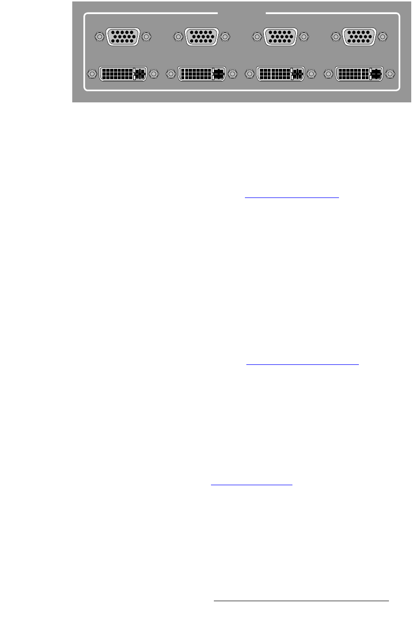
The figure below illustrates the Outputs Section:
Figure 2-3. BlendPRO-II Outputs Section
The Outputs Section includes four digital and four analog outputs:
~ DVI — the four DVI digital outputs are per DDWG 1.0 specifications. All
four are DVI-D (digital, single link, receptacle) using DVI-I connectors.
The DVI outputs are of the same resolution as the inputs.
In Appendix A, refer to the “DVI Connector Pinouts” section on page 38
for pinout details.
~ Analog — the four HD-15 analog outputs provide progressive RGB.
Analog syncs can be configured for 5 wire (RGBHV), 4 wire (RGB
composite sync) or 3 wire (sync on green) operation. Please note:
• Video components are driven at 700mV peak amplitude (1V for
SOG) at 75 Ohm terminations.
• Sync components (4 and 5 wire) are driven at TTL compatible
levels at 75 Ohm terminations.
• The analog outputs is driven at the same resolution and in sync
with the DVI outputs.
• Data is identical to the data on the DVI outputs, except that the
analog circuits are 10-bit, and thus preserve the 10-bit result of
the data doubling and feathering operations.
In Appendix A, refer to the “Analog 15-pin D Connector
” section on
page 37 for pinout details.
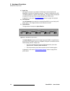
7) Ethernet Port
One RJ-45 (Neutrik) connector is provided for Ethernet communications with
BlendPRO-II. Ethernet is the primary means of controlling the BlendPRO-II.
Please note:
~ The Ethernet port is 10/100 Mbit auto-sensing capable.
~ The port is primarily configured to run as a DHCP client, although static
IP can be used if desired.
In Appendix A, refer to the “Ethernet Connector” section on page 39 for pinouts.
OUTPUTS
1234
1234


