18 BlendPRO-II • User’s Guide
2. Hardware Orientation
BlendPRO-II Rear Panel
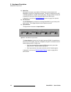
3) Serial Port
One 9-pin D connector is provided for RS-232 serial communications with
BlendPRO-II, typically for diagnostic purposes. The port is configured as a DCE,
115K Baud, 8 data bit, 1 stop bit, and no parity bits. The port can be connected to
a standard PC serial port with a straight through DB-9 to DB-9 cable.
In Appendix A, refer to the “Serial Connector” section on page 40 for pinouts.
4) AC Connector
One AC Connector is provided for connecting BlendPRO-II to your facility’s AC
power source. The integral switch turns the chassis on and off.
5) Inputs Section
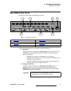
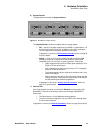
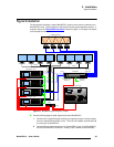
The figure below illustrates the Inputs Section:
Figure 2-2. BlendPRO-II Inputs Section
The Inputs Section includes four DVI digital inputs per DDWG 1.0 specifications.
All four are DVI-D (digital, single link, receptacle) using DVI-I connectors to allow
flexible cabling choices. Please note:
~ Each input accepts DVI progressive RGB signals with a pixel clock
speed from 25 - 162MHz (1600x1200x60Hz).
~ Each input must be of the same resolution and H/V locked together.
In Appendix A, refer to the “DVI Connector Pinouts
” section on page 38 for
pinout details.
INPUTS
1234


