


5-4
Connections
5975938 BARCOREALITY 9200TCR+ 020798
RGB V
RGB
H / C
V
H
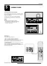
RS 232 IN
REMOTE
PROJECTOR MODE :
GREEN - OPERATI ON
RED - STANDBY
COMMUNICATION PORT
(800-PERIPHERALS)
RS232 OUT
IR-ACKNOWLEDGED
IR-RECEIVED
DIAGNOSTICS
CODE
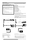
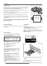
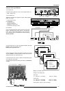
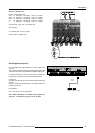
Fixed 5-Input Slot (slot 2)
Slot 2 has 5 BNC input terminals.
The following signals can be connected to these BNC connectors :
Connector name R G B H V
Input signal
RGBHV R G B H V
RGBS R G B S -
RGsB R Gs B - -
Composite Video - Video - - -
Super Video - Y - - C
Component Video - SS R-Y Y B-Y S -
Component Video - SOY R-Y Ys B-Y - -
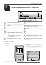
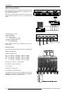
Slot 2 selection :
Key in 2 on the RCU or the local keypad.
Selection of the signal format on the 'Input slot' menu.
To change the signal format, press ADJUST or ENTER key to
start up the Adjustment mode.
Push the control disc up or down to select Installation and press
ENTER.
Use the control disc to select 'Input Slots' by pushing up or down
and press ENTER. The internal system will scan the inputs and
displays the result in the 'Input Slots' menu.
Push the control disc up or down to select the second slot. To
change the input signal priority, press ENTER key to toggle.
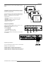
Possible indication :
RGB-SS [CS or HS&VS] = RGB analog signals, separate sync
is composite sync or horizontal and vertical sync.
RGB-SS [3LSS or CV] = RGB analog signals, separate sync
is composite tri-level sync or composite video.
RGB-SOG [SOG or 3LSOG] = RGB analog signals, sync on
green is composite sync or composite tri-level sync.
COMPONENT VIDEO - SS [SS or 3LSS] = separate sync is
composite sync or composite tri-level sync.
COMPONENT VIDEO - SOY [SOY or 3LSOY] = component
video with composite sync on Y or composite tri-level sync
on Y.
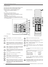
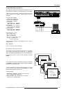
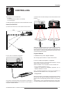
VIDEO
S-VIDEO
Select with or
then <ENTER>
<EXIT> to return.
Select with or
then <ENTER>
<EXIT> to return.
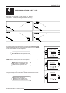
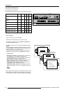
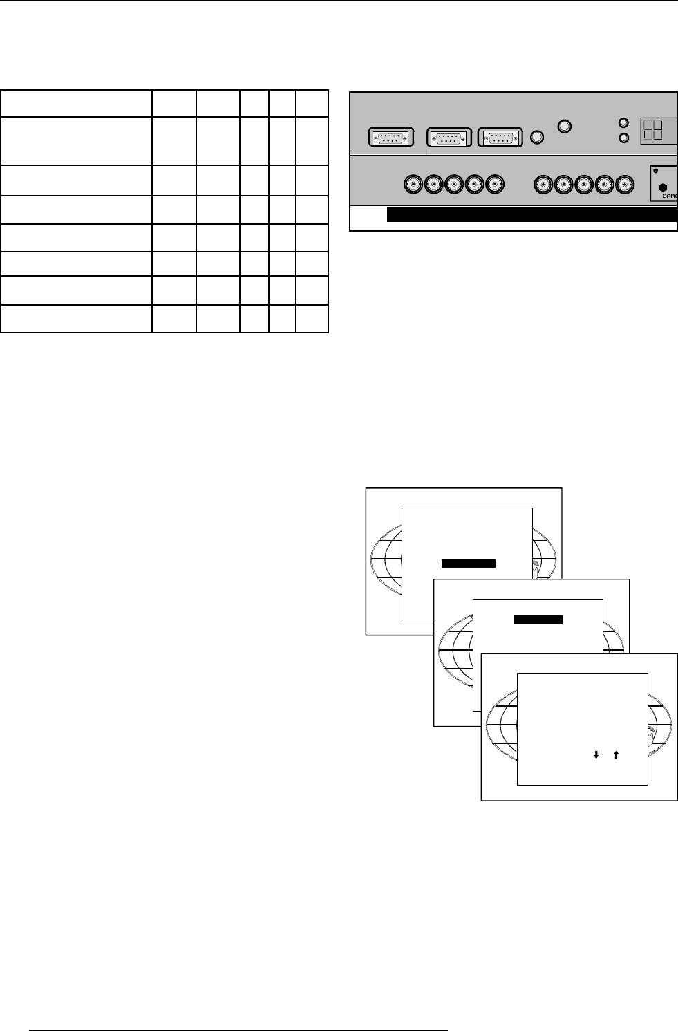
ADJUSTMENT MODE
Select a path from below :
RANDOM ACCESS
INSTALLATION
SERVICE
INSTALLATION
INPUT SLOTS
800 PERIPHERAL
CONVERGENCE
CONFIGURATION
INPUT SLOTS
Slot Module type [Config]
1. RGB-SS [CV]
2. RGB-SOG
3. Video [Video]
4. Component Video
Select with or
<ENTER> to toggle
<EXIT> to return.
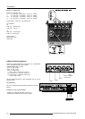
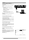
When using an RCVDS 05 with a 5 cable output module, connect
these 5 cables to this fixed 5-input slot (slot2) of the projector.
All sources of the RCVDS can now be accepted by the projector.