


Using the BayStack 303 and 304 Ethernet Switches
1-4 893-01010-A
.
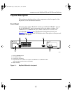
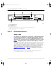
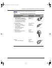
1 = One 10/100BASE-TX port
2 = 24 10BASE-T ports
3 = Console port connection
4 = Expansion slot for the addition of an optional 10/100BASE-TX or 100BASE-FX MDA
(switch should be powered down to install MDA)
5 = LED status indicators
Figure 1-2. BayStack 303 switch front panel
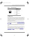
10BASE-T Ports
The 10BASE-T port connections are provided for the 10 Mb/s Ethernet segment
or nodes to attach to the BayStack 303 and 304 Ethernet Switches. The RJ-45
jacks accept standard Category 3, 4, or 5 copper unshielded twisted pair (UTP)
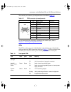
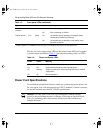
cable connections. Pin assignments for the standard RJ-45 connector are given in
T
able 1-1. The BayStack switches are shipped with the 10BASE-T connectors
configured as MDI-X (media-dependent interface-crossover). These ports connect
over straight cables to the network interface controller (NIC) card in a node or
server, similar to a conventional Ethernet repeater hub. If you are connecting to
another Ethernet hub or Ethernet switch, you need a crossover cable unless an
MDI connection exists on the associated port of the attaching device (see
“
Connecting 10BASE-T Ports” on page 2-8 for a description of the crossover
cable).
The 10 Mb/s ports operate in half-duplex mode only, and each port has an
associated LED that indicates link status of the line.
303
Console
100BASE-TX
MDA
1357911
225 4 6 8 10 12
13 15 17 19 21 23
14 16 18 20 22 24
Power Status
100BASE-TX
Link
100
F Dx
1357911
24681012
13 15 17 19 21 23
14 16 18 20 22 24
896EB
1
4
32
5
89301010.BK Page 4 Tuesday, June 10, 1997 8:00 PM