


Index-2 893-01010-A
D
data rate, A-1
DB-9 connector, 1-6
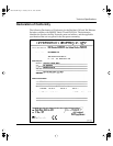
Declaration of Conformity, A-3
Default Gateway Address field, 3-13
default settings, 2-15
deferred transmissions, 3-11
Designated Root, 3-8
desktop switch, 3-19
devices, attaching to the switch, 2-9
diagnostics, 4-1
duplex indicator, 2-11
E
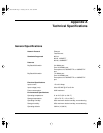
electrical specifications, A-1
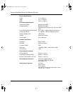
electromagnetic specifications, A-2
environmental specifications, A-1
Esc key, 3-4
Exit Telnet option, 3-17
expansion slot, 1-6
F
F Dx LED, 1-8, B-2, B-4
factory default settings, 2-15
features, 1-1
fiber media adapter, B-2
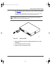
flat surface, installing on, 2-2
Forward Delay, 3-8
front panel, 1-3
full-duplex, 1-5, 2-10
G
gateway address, 2-18
grounding the switch, 2-2
H
half-duplex, 1-4, 2-10
hardware architecture, A-2
Hello Time, 3-8
high-speed port
configuration
, 3-14
connection, 1-6, 2-10
Hold Time, 3-9
I
installation
attaching devices
, 2-8
default setup, 2-15
flat surface, 2-2
metal chassis in a rack, 2-5
plastic chassis in a rack, 2-6
requirements, 2-1
switch, 2-2
tools, 2-1
troubleshooting, 4-4
international power cord specification, 1-9
IP address
field
, 3-13
format of, 2-19
setting, 2-18
IP subnet mask field, 3-13
L
Language Selection Menu, 2-16, 3-6
LEDs
10/100BASE-TX MDA
, B-4
100, 1-8
100BASE-FX MDA, B-2
F Dx, 1-8
front panel, 1-7
Link, 1-7, 2-9, B-2, B-4
link status, troubleshooting, 4-6
LinkUp/LinkDown Trap Generation parameter, 3-16
89301010.BK Page 2 Tuesday, June 10, 1997 8:00 PM