


8 2IQEC2/43798 Manual
B&B Electronics -- PO Box 1040 -- Ottawa, IL 61350
PH (815) 433-5100 -- FAX (815) 433-5105
Software Registers
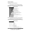
Flag Register (Read Data Address)
The FLAG register is a read-only register that holds the
status information of the counters and can be read out on the data
bus. To read the FLAG byte for any axis, read the control address
of that axis.
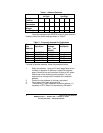
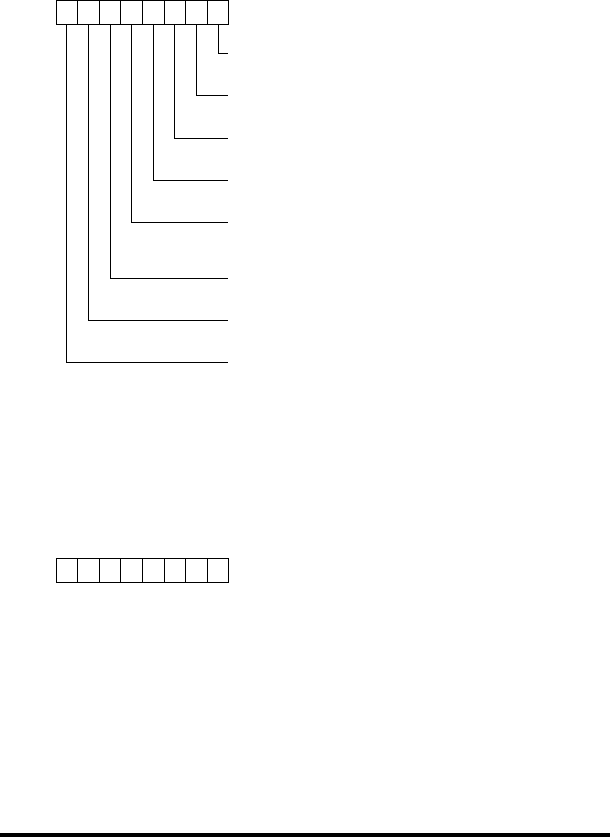
FLAG Byte Defined
76543210
BT: Borrow toggle flip-flop.
Toggles every time CNTR underflows
CT: Carry toggle flip-flop.
Toggles every time CNTR overflows
CPT: Compare toggle flip-flop.
Toggles every time PR equals CNTR.
S: Sign flag. Set to 1 when CNTR underflows.
Reset to 0 when CNTR overflows
E: Error flag. Set to 1 when excessive noise is present at
the count inputs in quadrature mode. Irrelevant in non-
quadrature mode.
U/D': Up/Down flag. Set to 1 when counting up
And reset to 0 when counting down
IDX: Index. Set to 1 when selected index input is at active
level.
0: Not used. Always reset to 0.
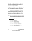
Reset and Load Signal Decoders (Write to Control Address)
The following functions can be performed by writing to the
control address for that axis. Note that bits 5 and 6 define the
register and should always be zero when writing to the RLD register.
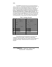
RLD Byte Defined
76543210
X00XXXX0NOP
X00XXXX1ResetBP
X00XX00XNOP
X 0 0 X X 0 1 X ResetCNTR
X 0 0 X X 1 0 X ResetBT,CT,CPT,S
X00XX11XResetE
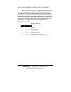
X0000XXXNOP
X0001XXXTransferPRtoCNTR
X0010XXXTransferCNTRtoOL
X0011XXXTransferPR0toPSC
000XXXXXSelecttheRLDaddressed by X'/Y input
100XXXXXSelectbothXRLDandYRLDorZRLDandWRLDtogether