


2IQEC2/43798 Manual 5
B&B Electronics -- PO Box 1040 -- Ottawa, IL 61350
PH (815) 433-5100 -- FAX (815) 433-5105
IRQ
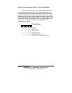
The 2IQEC2/4 card allows the use of interrupts (IRQ) 2-7,
10-12, 14, and 15. This interrupt is shared with all the channels. To
determine the channel that caused the interrupt, the interrupt
service routine must read the address located at the base address
plus 8. The lower nibble will indicate which channel caused the
interrupt. Where bit 0 is the X-Axis, bit 1 is the Y-Axis, bit 2 is the Z-
Axis, and bit 3 is the W-Axis. The upper nibble is not used. To
clear the interrupt, the interrupt service routine must read or write to
the address located at base address plus 12 (0xC). The IRQ is set
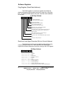
by placing a jumper on JP1. Only one jumper should be placed on
JP1 at any one time. Check Table 3 for common interrupt uses.
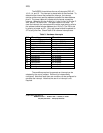
The conditions required to generate an interrupt can be
selected by the use of jumpers. Each axis is independently
configured. Note that more than one condition can be configured to
generate the interrupt. Note that the use of an interrupt is not
required.
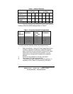
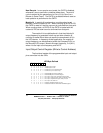
Table 3. Hardware Interrupts
IRQ AT machines XT machines
2 routed to IRQ controller 2 Reserved
3 serial port COM2,4 Serial port COM2,4
4 serial port COM1,3 Serial port COM1,3
5 LPT2 hard disk
6 floppy disk Floppy disk
7 LPT1 parallel printer port 1 (LPT1)
8 real-time clock not available
9 re-directed to IRQ2 not available
10 Unassigned not available
11 Unassigned not available
12 Unassigned not available
13 Coprocessor not available
14 hard disk not available
15 Unassigned not available