


10 2IQEC2/43798 Manual
B&B Electronics -- PO Box 1040 -- Ottawa, IL 61350
PH (815) 433-5100 -- FAX (815) 433-5105
Non-Recycle. In non-recycle count mode, the CNTR is disabled,
whenever a count overflow or underflow takes place. The end of
cycle is marked by the generation of a Carry (in Up Count) or a
Borrow (in Down Count). The CNTR is re-enabled when a reset or
load operation is performed on the CNTR.
Modulo-N. In modulo-N count mode, a count boundary is set
between 0 and the content of PR. When counting up at CNTR=PR,
the CNTR is reset to 0 and the up count is continued from that point.
When counting down, at CNTR=0, the CNTR is loaded with the
content of PR and down count is continued from that point.
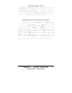
The modulo-N is true bidirectional in that the divide-by-N
output frequency is generated in both up and down direction of
counting for same N and does not require the complement of N in
the UP instance. In frequency divider application, the modulo-N
output frequency can be obtained at either the Compare(FLG1) or
the Borrow(FLG2) output. Modulo-N output frequency, f
N=fI/(N+1)
where f
I is the input count frequency and N=PR.
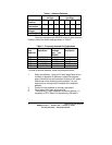
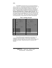
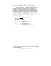
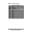
Input/Output Control Register (Write to Control Address)
The functional modes of the programmable input and output
pins are written into the IORs.
IOR Byte Defined
76543210
X10XXXX0Disableinputs A and B
X10XXXX1Enable inputs A and B
X 1 0 X X X 0 X LCNTR'/LOL'pin is Load CNTR input
X 1 0 X X X 1 X LCNTR'/LOL'pin is Load OL input
X 1 0 X X 1 X X RCNTR'/ABGpin is Reset CNTR input
X 1 0 X X 0 X X RCNTR'/ABGpin is A and B Enable gate
X1000XXXFLG1pinisCarry'output,FLG2pinisBorrow'output
X1001XXXFLG1pinisCompare'output,FLG2pinisBorrow'output
X1010XXXFLG1pinisCarry'/Borrow'output,FLG2pinisU/D'
X1011XXXFLG1pinisIDX,FLG2isE
010XXXXXSelecttheIORaddressed by X'/Y input
110XXXXXSelectbothXIORandYIORorZIORandWIORtogether