


6 2IQEC2/43798 Manual
B&B Electronics -- PO Box 1040 -- Ottawa, IL 61350
PH (815) 433-5100 -- FAX (815) 433-5105
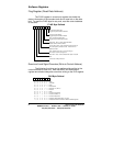
Configuring the jumpers
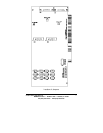
The jumpers located on the left side of the card make it
easy to configure the card to your individual needs. The jumpers
are grouped by axis and function. The top group of jumpers is for
the X axis. Then next groups going down are for the Y-axis, Z-axis,
and W-axis respectfully. There are three signals that can be routed
via these jumpers. They are the FLG1 and FLG2 outputs from the
counter chips, and the index from the encoder. The FLG1 and
FLG2 outputs are software configurable. The FLG1 can be
configured to act as a carry (pulse on counter overflow), compare
(pulse when counter equals the preset register), index, or carry and
borrow (pulse on either an overflow or an underflow of the counter).
The FLG2 can be configured to act as a borrow, up-down indicator,
or an error flag. These outputs are brought to the user connectors.
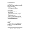
The first jumpers labeled JP4, JP8, JP12 and JP16 allow
you to select what conditions cause the counter to be loaded with
the preset value in the preset register. The middle jumpers labeled
JP3, JP7, JP11, and JP15 allow you to select what conditions cause
the counter to be reset or the counter to be enabled depending on
the software configuration of the input. The last jumpers labeled
JP2, JP6, JP10, and JP14 are used to define what conditions cause
an interrupt (IRQ).
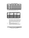
JP5 selects the type of input encoder signals for the X and
Y axes not including the index. Set jumper JP5 for RS-422
differential mode and remove the jumper for TTL level encoder
input. When in differential mode the TTL output of the differential
receivers is present at the TTL pins. Leave these pins unconnected
in differential mode.
JP13 selects the type of input encoder signals for the Z and
W axis not including the index. Set jumper JP13 for RS-422
differential mode and remove the jumper for TTL level encoder
input. When in differential mode the TTL output of the differential
receivers is present at the TTL pins. Leave these pins unconnected
in differential mode.
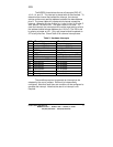
JP9 selects the type of input from the index pins. This
jumper affects all the axes' index inputs. Set jumper JP9 for RS-422
differential mode and remove the jumper for TTL level encoder
input. When in differential mode the TTL output of the index
receivers is present at the TTL pins. Leave these pins unconnected
in differential mode.