


2IQEC2/43798 Manual 9
B&B Electronics -- PO Box 1040 -- Ottawa, IL 61350
PH (815) 433-5100 -- FAX (815) 433-5105
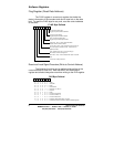
Filter Clock Prescalers
Each PSC is an 8-bit programmable modulo-N down
counter, driven by the FCK clock. The factor N is downloaded into a
PSC from the associated PR low byte register PR0. The PSCs
provide the ability to generate independent filter clock frequencies
for each channel.
Final filter clock frequency
FFCKn=f
FCK/(n+1), where n=PSC=0 to 255
Counter Mode Registers (Write to Control Address)
The counter’s operational mode is programmed by writing a
byte into the counter mode registers (CMRs).
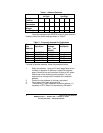
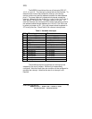
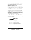
CMR Byte Defined
76543210
X01XXXX0BinaryCount
X01XXXX1BinaryCoded Decimal Count
X 0 1 X X 0 0 X NormalCount
X 0 1 X X 0 1 X RangeLimit
X 0 1 X X 1 0 X Non-RecycleCount
X 0 1 X X 1 1 X Modulo-N
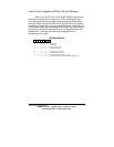
X0100XXXNon-quadrature
X0101XXXQuadrature 1X
X0110XXXQuadrature 2X
X0111XXXQuadrature 4X
001XXXXXSelecttheCMRaddressed by X'/Y input
101XXXXXSelectbothXCMRandYCMRorZCMRandWCMR
together
Definitions of count modes
Range Limit. In range limit count mode, an upper and a
lower limit is set, mimicking limit switches in the mechanical
counterpart. The upper limit is set by the contents of the PR and the
lower limit is set to be 0. The CNTR freezes at CNTR=PR when
counting up and at CNTR=0 when counting down. At either of these
limits, the counting is resumed only when the count direction is
reversed.