


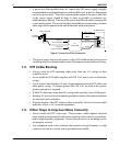
The cable shield must not be used as the signal ground.
It is tempting to try and reduce the cost of 5-wire cabling by using a 4-wire cable
with the shield used as the signal ground. DON’T DO IT. The initial cost savings
are always exceeded by the maintenance costs once the system is operating under
field conditions. It is often necessary to completely replace the network com-link
with the proper cable (5-wire plus shield) toeliminate noise problems in the system.
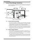
The signal ground must not be connected to the chassis or earth ground.
The chassis or earth ground is intended as a safety ground for power supplies, EMI
filters, voltage spike protection circuits, 120 VAC neutral returns, and all manner of
AC and DC driven devices. As a result, the chassis or earth ground can carry large
voltage potentials and currents. Connecting the signal ground to chassis or earth
ground can damage the devices connected to the com-link.
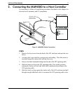
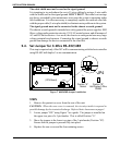
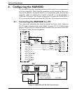
2.4. Set Jumper for 3-Wire RS-422/485
This step is required only if the OIT will be communicating with the host controller
using RS-485 half-duplex 3-wire communication.
STEPS
1. Remove the protective cover from the rear of the unit.
CAUTION: When the rear cover is removed, the circuitry inside is exposed to
possible damage by electrostatic discharge. Refer toStatic Awareness on page 4.
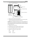
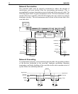
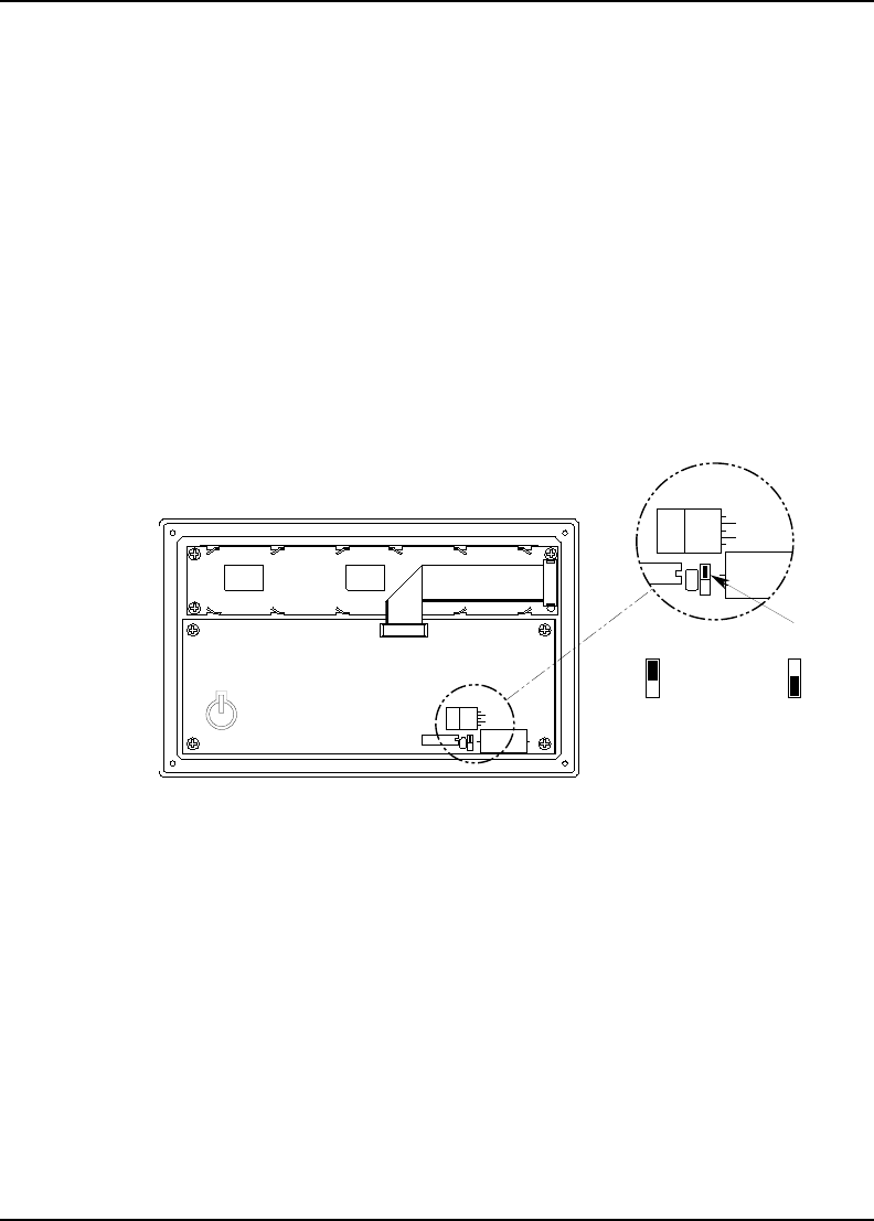
2. Locate jumper “JP4” using Figure 7 as a guide. The jumper is installed on
the upper two pins of a 3-pin header. This is called Position “A”.
3. Move the jumper to the lower two pins of the 3-pin header (Position “B”).
Ensure that the jumper is pressed fully into place.
4. Replace the rear cover and the four retaining screws.
INSTALLATION MANUAL 13
1010-0046A, REV 00
JP4
B
A
Normal
A
Position "A",
Half-Duplex 3-Wire
Position "B",
JP4
RS485
B
(Display)
(CPU Board)
B
JP4
A
Figure 7 MAP450D Jumper Installation