


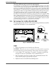
IMPORTANT: When panel mounting the MAP450D, do not catch the display
connector on the panel cutout. The display is exposed while panel mounting and
extra care should be taken. The display can be damaged if the display cable
connector, which protrudes from the panel cutout, is touching the panel when
tightened. To avoid damage, place the MAP450D gently onto the panel while
monitoring for this condition.
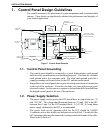
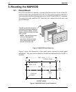
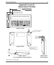
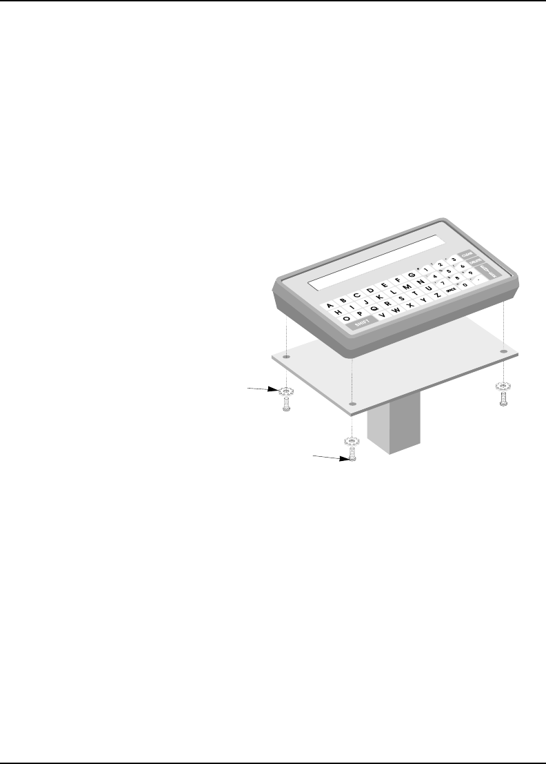
3.2. Pedestal/Pendent Mount
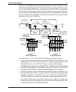
The OIT is installed onto a pedestal/pendent by removing the four rubber feet from
the rear cover of the OIT, then attaching the OIT to a mounting plate using the four
pre-tapped holes in the rear cover. The OIT enclosure and cable strain relief provide
the environmental seal to NEMA 4 and NEMA 12 standards.
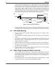
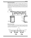
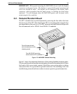
Figure 11 shows the minimum dimensions of the pedestal/pendant mounting plate.
The area on the pedestal/pendant mounting plate around the mounting holes (where
the heads of the screws make contact) should have any existing paint or plating
removed to allow for a good chassis ground connection. The mounting screws are
installed using external tooth star washers to ensurea positive ground connection.
INSTALLATION MANUAL 15
1010-0046A, REV 00
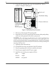
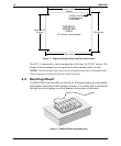
Four #6-32UNC mounting
screws secure OIT to
p
edestal
Four #6 external tooth
star lockwashers provide
chassis ground
Figure 10 MAP450D Pedestal Mounting