


3. Mounting the MAP450D
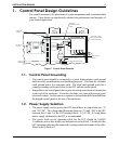
3.1. Panel Mount
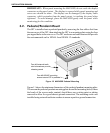
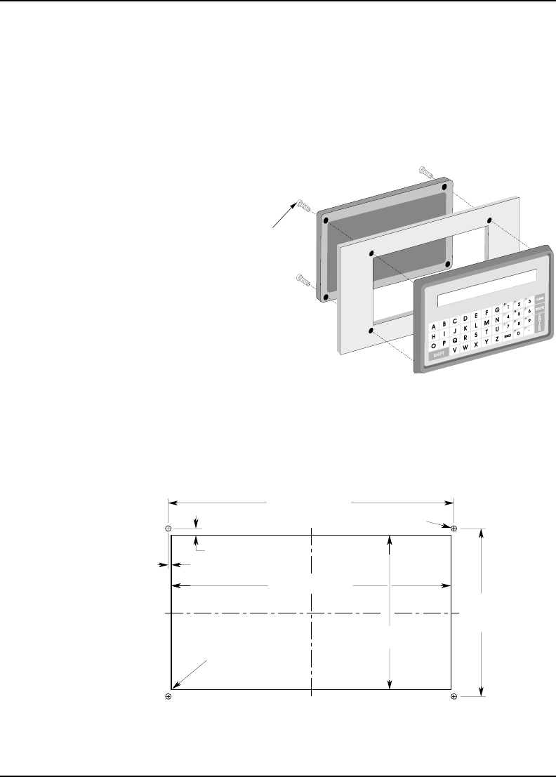
The OIT is installed in a panel by separating the front and rear covers of the OIT,
and then sandwiching the panel between the two. The gasketed surface of the OIT’s
front cover provides the environmental seal to NEMA 4 and NEMA 12 standards.
The rear cover helps shield the OIT from dust, dirt, induced electrical noise, and
physical damage.
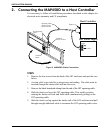
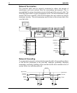
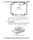
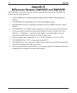
Figure 9 shows the dimensions of the panel cutout required for proper panel
installation. The panel cutout should be cleaned and deburred before the OIT is
installed.
14 MAP450D
1010-0046A, REV 00
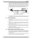
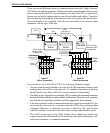
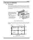
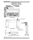
The OIT is mounted using four
#6-32UNC screws sandwiching
the OIT halves to panel. Screw
length is equal to panel thickness
plus 1/2 inch.
NOTE: The mounting screws
must not be torqued to
more than 18 pound-inches.
Over-torquing can strip the
threads in the front half.
Figure 8 MAP450D Panel Mounting
0.156 dia., 4 holes
7.460 +/-0.015
4.100
7.580 +/-0.010
4.460
0.180 +/-0.015
+/-0.010
+/-0.015
0.060 +/-0.015
R 0.03 max.,
4 places
C
L
C
L
FRONT VIEW
Figure 9 MAP450D Panel Cutout Dimensions