


1. Control Panel Design Guidelines
Pay careful attention to the placement of system components and associated cable
routing. These items can significantly enhance the performance and integrity of
your control application.
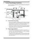
1.1. Control Panel Grounding
• The control panel should be connected to a good, high-integrity earth ground
both for safety considerations and shielding purposes. This must be a reliable
earth ground with a low-resistance path. The ideal earth ground would be a
copper grounding rod located close to the OIT and the control panel.
• Hinged doors on control panels do not provide a long term electrical connection
to the rest of the enclosure. Corrosion develops over time and prevents good
electrical contact. For this reason, a separate wire braid should be installed from
the hinged control panel to the rest of the enclosure.
1.2. Power Supply Selection
• The power supply used to power the OIT should have an output between +12
and +30 VDC. The voltage should measure between +12 and +30V at the OIT
between Pins 2 and 3 of the OIT terminal block. A 24 VDC, 0.5 amp linear
power supply dedicated to the OIT is recommended.
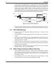
• The power leads on the operating cable for the OIT should be 18AWG
2-conductor wire with a shield wire and protective shield foil. The shield of the
OIT operating cable must be connected to earth ground at both ends of the cable.
Please refer to Section 2.
INSTALLATION MANUAL 5
1010-0046A, REV 00
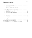
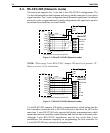
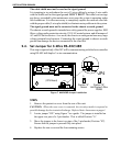
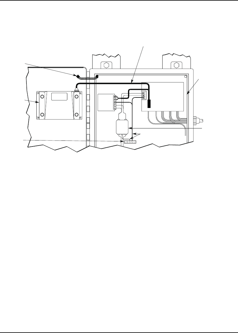
I / O CONTROL LINES
CONTROLLER
GROUND WIRES
OIT REAR
COVER
GROUND
STRAP
POWER LINE
FILTER
QUIET GROUND(ISOLATED)
QUIET
GROUND
LINE
FILTER
OIT
POWER
SUPPLY
OIT
SHIELDED
COMMUNICATION
CABLE
CONTROL PANEL
TIED TO RELIABLE
EARTH GROUND
CABLE
OIT OPERATING
Figure 1 Control Panel Example