


8 SDAIBB1300 Manual
B&B Electronics Mfg Co Inc – 707 Dayton Rd - PO Box 1040 - Ottawa IL 61350 - Ph 815-433-5100 - Fax 815-433-5104
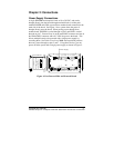
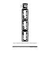
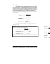
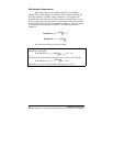
To support all 11 channels on the SDAxx modules connect 3
SDAIBBs to the I/O port of the SDAxx as shown in Figure 2 on page 4 and
set one board to JP9, one to JP10, and the last to JP11. This will provide
11 independent buffered inputs.
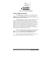
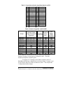
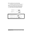
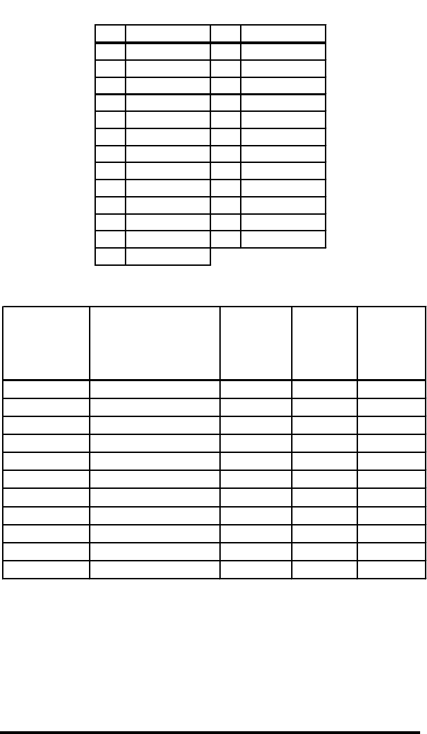
Table 3: Connections when the 4-position shunt is on JP11
Pin Connection Pin Connection
1 --- 14 ---
2 Power 15 ---
3 --- 16 ---
4 --- 17 ---
5 --- 18 ---
6 --- 19 ---
7GND20 ---
8 --- 21 ---
9 --- 22 ---
10 --- 23 A output
11 --- 24 B output
12 --- 25 C output
13 ---
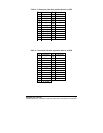
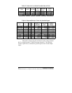
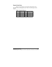
Table 4: Models Compatible with SDAIBB
Model
Channel Select
Jumper Connections
Supported
Channels
Supported
Power on
pins 2
and 7
2.5V
Output
Offset
Available
485SDA10 JP9
,
JP10
,
JP11 0-10 Yes Yes
485SDA12 JP9
,
JP10
,
JP11 0-10 Yes Yes
232SDA10 JP9
,
JP10
,
JP11 0-10 Yes Yes
232SDA12 JP9
,
JP10
,
JP11 0-10 Yes Yes
232SPDA JP9 0-3 Yes Yes
232SPDACL JP9 0-3 Yes Yes
485SPDA JP9 0-3 Yes Yes
485SPDACL JP9 0-3 Yes Yes
232OPSDA * 4 and 5 No No
ADIO12 JP9 4-7 No No
ADIO10 JP9 4-7 No No
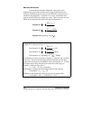
Set the jumper for any position and use the solder pads on the DB25
connector to bring out connections for channels 4 and 5. The other
channels already have selectable gains.