


Figure 3.1:Chassis Grounding Connection ................... 18
3.3
Connecting Power
...........................................................
19
3.4
Installing a Hard
Disk
.....................................................
19
3.5
BIOS Setup and
System
Assignments
............................
19
Appendix A System Settings and Pin Assignments ..........22
A.1
System
I/O
Address
and Interrupt
Assignment............
22
Table A.1: UNO-2170 System I/O Ports ...................... 22
A.2
Board
Connectors and Jumpers.......................................
24
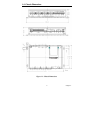
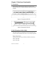
Figure A.1:UNO-2170 conn. and jp. locations (fs) ...... 24
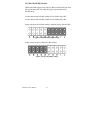
Figure A.2:UNO-2170 conn. and jp. locations (bs)...... 24
A.3
RS-232 Standard Serial Port
(COM1~COM2)
...............
26
A.4
RS-232/422/485 Serial Port (COM3~COM4)
................
27
A.5
Ethernet RJ-45 Connector
(LAN1~LAN2)
.....................
27
A.6
Phoenix Power Connector (PWR)...................................
28
A.7
PS/2 Keyboard and
Mouse
Connector
............................
28
A.8
USB Connector
(USB1~USB2)
......................................
29
A.9
VGA Display
Connector
.................................................
29
Appendix B Programming the Watchdog Timer .............32
UNO-2170 User Manual vi