


15
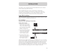
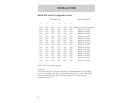
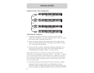
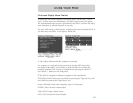
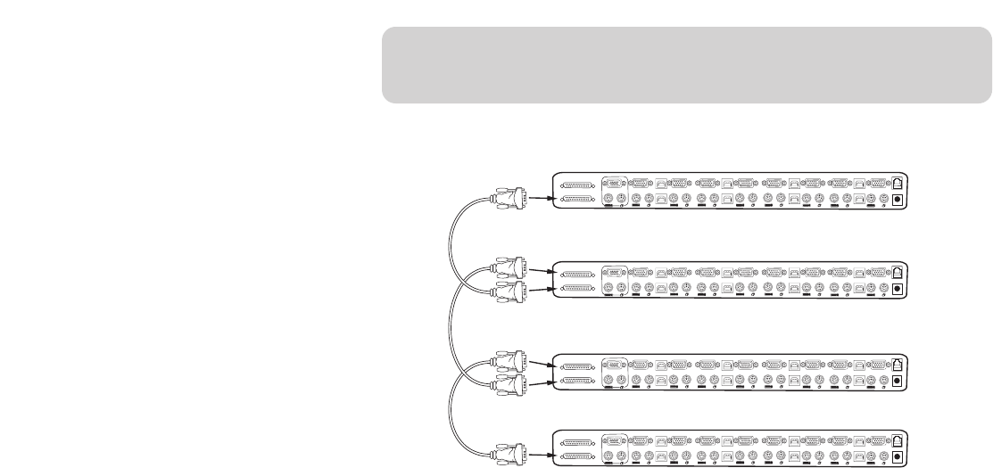
Example of Daisy-Chain Configuration:
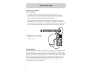
Connecting the Computers:
9. Connect all computers to the Master and Slave switches. Refer to
“Single PRO2 Installation” on page 10 for instruction on how to connect
the Console and the computers to the PRO2.
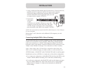
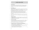
10. Connect the power supply to the Master switch. Power up the Master
switch. You should see the Master switch light up and display the digits
“00”, indicating its BANK address.
11. Power up the Slave switches sequentially, beginning with Bank 01, by
connecting each unit’s power supply. Each switch should display its
corresponding BANK address number as it is powered up.
Note: If the PRO2s do not enumerate correctly, reset the Master switch
(BANK 00) by simultaneously pressing the "BANK +" and "BANK –" buttons.
You can also reset the Master switch to detect newly added Slave switches.
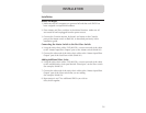
If the switches still do not enumerate correctly, check that all switches have
the correct BANK address assigned to them and that all daisy-chain cables
are connected properly.
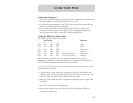
12. Verify that the Master unit has detected all Slave switches by scrolling
through the BANKS using the BANK up and BANK down buttons.
If all Slave switches are detected properly, the LED display on the Master
switch will register and display the attached Slave switch’s BANK address.
INSTALLATION
VGA
VGA
VGA
VGA
VGA
VGA
VGA
VGA
VGA
08
08
08
USB
USB
USB
USB
USB
USB
USB
USB
07
07
07
06 06
06
06
05
05
05
04
04
04
03
03
03
02
02
02
01
01
01
VGA
VGA
VGA
VGA
VGA
VGA
VGA
VGA
VGA
08
08
08
USB
USB
USB
USB
USB
USB
USB
USB
07
07
07
06 06
06
06
05
05
05
04
04
04
03
03
03
02
02
02
01
01
01
VGA
VGA
VGA
VGA
VGA
VGA
VGA
VGA
VGA
08
08
08
USB
USB
USB
USB
USB
USB
USB
USB
07
07
07
06 06
06
06
05
05
05
04
04
04
03
03
03
02
02
02
01
01
01
VGA
VGA
VGA
VGA
VGA
VGA
VGA
VGA
VGA
08
08
08
USB
USB
USB
USB
USB
USB
USB
USB
07
07
07
06 06
06
06
05
05
05
04
04
04
03
03
03
02
02
02
01
01
01
S
l
ave
I
npu
t
M
as
t
e
r
I
npu
t
/S
l
ave
O
u
t
pu
t
S
l
ave
I
npu
t
M
as
t
e
r
I
npu
t
/S
l
ave
O
u
t
pu
t
S
l
ave
I
npu
t
M
as
t
e
r
I
npu
t
/S
l
ave
O
u
t
pu
t
S
l
ave
I
npu
t
M
as
t
e
r
I
npu
t
/S
l
ave
O
u
t
pu
t
cable 1
cable 2
cable 3
Master unit (BANK 00)
Slave unit (BANK 01)
Slave unit (BANK 02)
Slave unit (BANK 03)