


22
7
th
byte The highest byte of output voltage value
8
th
to 25
th
byte System reserve
26
th
byte Check sum
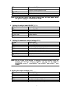
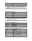
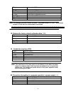
5. Setting the output current (24H)
1
st
byte Start bit ( AAH )
2
nd
byte Address (0~0XFE)
3
rd
byte
Command( 24H)
4
th
byte To set the low byte of current value
5
th
byte To set the high byte of current value
6
th
to 25
th
byte System reserve
26
th
byte Check sum
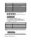
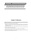
6. Setting the communication address (25H)
1
st
byte Start bit ( AAH )
2
nd
byte The current address of power supply(0~0XFE)
3
rd
byte Command(25H)
4
th
byte The new address
5
th
to 25
th
byte System reserve
26
th
byte Check sum
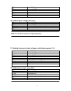
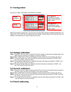
7. Reading the present current/voltage, maximum voltage, setup
voltage/current and the states of power supply. (26H)
1
st
byte Start bit ( AAH )
2
nd
byte Address(0~0XFE)
3
rd
byte
Command( 26H)
4
th
byte Byte 0 of present output current value
5
th
byte Byte 1 of present output current value
6
th
byte Byte 0 of present output voltage value
7
th
byte Byte 1 of present output voltage
8
th
byte Byte 2 of present output voltage
9
th
byte Byte 3 of present output voltage
10
th
byte Power supply’s state
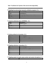
Note:
We use 4 bytes of Hex number to represent an output voltage value. For
example the output voltage value is 16.000V and the hex code of 16.000 is
0X00003EB0, so the 4
th
byte is 0XB0, 5
th
byte is 0X3E, 6
th
byte is 0X00, 7
th
byte
is 0X00.
Note:
We use 2 bytes of Hex number to represent an output current value. For
example the output current value is 1.000A, the hex code of 1.000 is 0X03E8,
so the 4
th
byte is 0XE8, 5
th
bye is 0XE3.