


23
11
th
byte To set the low byte of current value
12
th
byte To set the high byte of current value
13
th
byte Byte 0 of the maximum voltage value
14
th
byte Byte 1 of the maximum voltage value
15
th
byte Byte 2 of the maximum voltage value
16
th
byte Byte 3 of the maximum voltage value
17
th
byte Byte 0 of output voltage value
18
th
byte Byte 1 of output voltage value
19
th
byte Byte 2 of output voltage value
20
th
byte Byte 3 of output voltage value
21
st
to 25
th
byte System reserve
26
th
byte Check sum
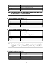
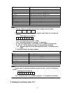
8. Entering the calibration mode( 27H)
1
st
byte Start bit(AAH)
2
nd
byte Address(0~0XFE)
3
rd
byte Command(27H)
4
th
byte Calibration protection state
5
th
byte Calibration password(0X28H)
6
th
byte Calibration password(0X01H)
7
th
to 25
th
byte System reserve
26
th
byte Check sum
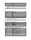
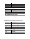
9. Reading the calibration state (28H)
Note:
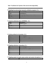
1. We use 4 bytes to represent the maximum voltage value as follows:
Byte 3 Byte 2 Byte1 Byte
0
2. We use 1 byte to represent power supply’s state. Each bit is defined as
follows:
From higher bit to lower bit
7 6 5 4 3 2 1 0
0 bit: The output state, 0 is OFF, 1 is ON.
1 bit: Over heat protection, 0 is normal, 1 is abnormal.
2? 3 bit: The output mode, 1 is CV mode, 2 is CC mode,3 is Unreg mode.
4? 5? 6 bit: The fan speed, 0 is stop, 5 is the maximum fan speed.
7 bit: Operation state, 0 is front panel operation mode, 1 is remote control
mode.
3. The frame format is the same as above
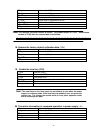
Note:
We use a byte to represent calibration protection state, each bit is defined as
follows:
from higher bit to lower bit
7 6 5 4 3 2 1 0
0 bit: Protection state, 0 is to disable protection, 1 is to enable the protection.