Chapter 3: Installation
724-746-5500 | blackbox.com
Page 11
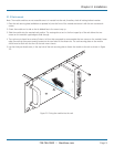
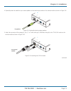
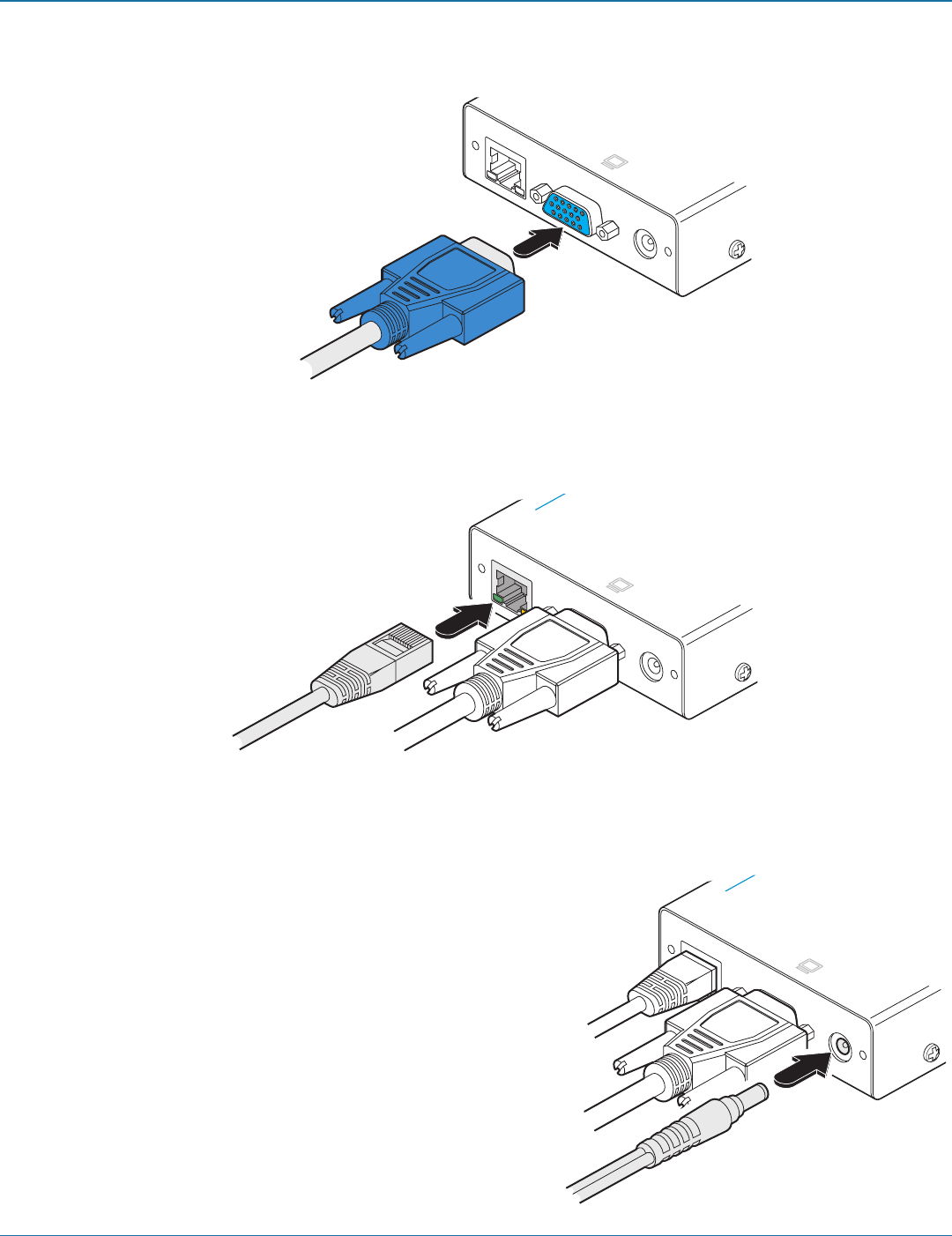
4 Optionally connect a local video monitor to the video out feed- through connector on the local module as shown in Figure 3-5:
Figure 3-5. Optionally attaching a local video monitor
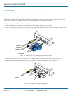
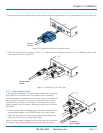
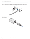
5 Attach the connector of the category 5, 5e, 6, 7 or 7a link cable (up to 1000 feet in length) to the ‘TO REMOTE’ socket on the
local module as shown in Figure 3-6:
Figure 3-6. Attaching the CATx link cable
LINK
POWER
OUT
TOREMOTE
ON
h Wizard VGA/ USB
™
K V M
E X T E N D E R
Link to remote
module
LINK
POWER
OUT
TOREMOTE
ON
h Wizard VGA/ USB
™
K V M
E X T E N D E R
To local
monitor
3.2.1.1 Local module power
In the majority of installations, the local module will derive all of its power
successfully from the USB link with the computer system. However, if
insufficient voltage is available from the computer system, the module will
fail to operate. If this occurs (or if you do not intend to use the USB con-
nection with the computer) you will need to purchase and use a power
adapter identical to the one used for the remote module from your Black
Box stockist.
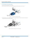
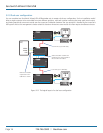
1 If external power input is necessary, attach the output connector of the
optional power adapter to the ‘POWER’ socket of the local module.
2 Attach the IEC power cord to the power adapter body and insert the
mains plug of the cord to a nearby power outlet.
Note: If a power adapter is plugged into the module but not switched on,
it will prevent the unit from deriving power from the USB connection.
LINK
POWER
OUT
TOREMOTE
ON
h Wizard VGA/U SB
™
K V M
E X T E N D E R
To optional
power adapter


