


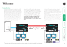

welcome contents
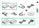
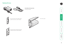
installation
operation
rter
inormation
9
®
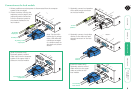
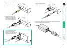
5 Optionally attach the lead from
your stereo speakers to the audio
output socket on the remote
module.
SR
X
TO
LOCAL
LINK
PO
WE
R
SHARPNESS
ON
®
5500
6 Attach the connector of the
category 5, 5e or 6 link cable
(up to 50 metres in length) to
the ‘TO LOCAL’ socket on the
remote module (labelled ‘LINK
1’ on dual VGA variants).
SRX
TO
LOCAL
LINK
PO
WE
R
SHARPNESS
ON
®
5500
SR
X
TO
LOCAL
LINK
PO
W
ER
SHARPNESS
B
A
ON
®
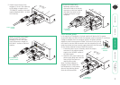
[Dual VGA variant only] Attach
the connector of a second
category 5, 5e or 6 link cable (up
to 50 metres in length) to the
‘LINK 2’ socket on the remote
module.
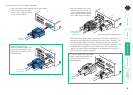
7
Attach the output connector
of the power supply to the
‘POWER’ socket of the remote
module.
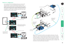
To speakers
Link to remote
module
Secondary
link to
remote
module
SR
X
TO
LOCAL
LINK
PO
WE
R
SHARPNESS
ON
®
5500
To power
supply
8 Attach the IEC power lead to the power supply body and insert the mains
plug of the lead to a nearby power outlet.
To mains
outlet