


welcome contents
installation
operation
rter
inormation
6
®
BLACK
BOX
LO
C
A
L
®
IN
IN
OUT
To speaker
output port
To USB port
To primary video
output port
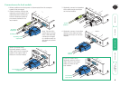
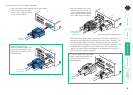
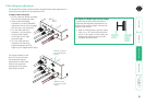
Connections at the local module
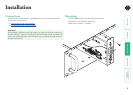
1 Where possible ensure that power is disconnected from the computer
system to be connected.
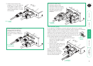
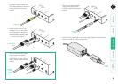
4 Optionally connect a local video
monitor to the video out feed-
through connector on the local
module.
3 Optionally connect local speakers
to the audio output connector
on the local module.
BLACK
BOX
LO
C
A
L
®
IN
IN
OUT
To local
speakers
SR
X
TO
R
EM
O
T
E
LIN
K
P
O
W
ER
O
N
®
6
5500
OU
T
To local
monitor
2 Attach the video, USB (see the
Important note on page 5) and
(optionally) audio connections
from the computer system to
the relevant sockets on the
local module.
[Dual VGA variant only]
Optionally attach a second
video input from the computer
system to the upper video in
socket on the local module.
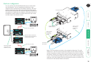
Note: The dual VGA
variant has its primary
video, USB and audio
connectors arranged
in a similar manner to
the single unit (shown
above).
LOCAL
®
IN
A B
IN
OU
T
To secondary video
output port
SR
X
TO
REMO
TE
LINK
PO
WER
ON
OUT
A
B
To secondary
local monitor
[Dual VGA variant only]
Optionally attach a second
video monitor to the upper
video out socket on the
local module.