


welcome contents
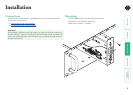
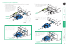
installation
operation
rter
inormation
11
®
Video display (DDC) information
The Display Data Channel (or DDC) is an industry standard scheme which allows
video monitors to declare their capabilities to the computer’s video adapter
circuitry, allowing the latter to optimise their outputs accordingly. Since the
widespread adoption of the scheme, video adapters have become increasingly
dependent on receiving relevant DDC information during startup, before they
will output anything more than a rudimentary video signal.
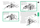
It is not possible to transmit DDC data back from the video monitor that is
attached to the remote module to the computer’s video adapter. Therefore,
during startup of the local module, it will search for a video monitor connected
to its local feed-through connector:
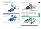
• If a local video monitor is found, its DDC information will be compared to
the information already stored and, if different, will be copied, stored and
presented to the video adapter upon request.
• If no local video monitor is found, the local module will make available its
previously stored set of DDC parameters to the video adapter upon request;
or, if none were stored, a default set.
In either case, the DDC information taken by the video adapter will be used
to determine the video output that is sent via the SRX modules to the remote
monitor.
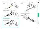
If you find that the default DDC information is not completely suitable for your
remote monitor, try temporarily connecting your remote monitor to the video
out port of the local module. When the local module is powered up, it will read
and store the DDC information from your monitor. You can then return the
monitor to its remote position and the new DDC information will be used at
every power on.
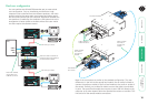
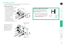
DDC indications
When power is first applied to the local module (either from
the computer’s USB port or an optional power adapter) it will
search for valid DDC data on its video out connector. During
this process, the yellow indicator (built into the link connector)
will flash to indicate its progress:
• If no valid DDC information is located, the yellow indicator
will give one very short flash, representing an attempt to
read data. No changes will be made to the information already stored within
the local module.
• If the DDC information is the same as that already stored, no change will be
made and the yellow indicator will give one single flash as the information is
checked and normal operation resumes.
• If different DDC information is located, the yellow indicator will flash rapidly
for 2 to 3 seconds while the new information is stored. A single flash will
then be given as the information is checked and normal operation resumes.
The local module’s yellow indicator also provides fault indications to assist with
troubleshooting:
• Two flashes - Checksum error prior to copying - no information will be
programmed.
• Three flashes - Too much data to fit into the module - the module can hold a
maximum of two pages of DDC information.
• Rapid flashing followed by four flashes - data was lost during copying - the
default data was substituted. Repeat the power on process.
• Rapid flashing followed by five flashes - Checksum error during copying
- the default data was substituted. Repeat the power on process.
LIN
K
O
REMO
TE
ON