


welcome contents
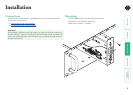
installation
operation
rter
inormation
7
®
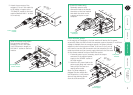
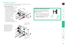
Local module power
In the majority of installations, the local module will derive all of its power
successfully from the USB link with the computer system. However, if insufficient
voltage is available from the computer system, the green indicator
adjacent to the link connector will flash. If this occurs (or if you do
not intend to use the USB connection with the computer) you will
need to purchase and use a power supply identical to the one used
for the remote module from your Black Box stockist.
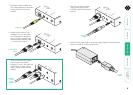
1 If external power input is necessary, attach the output
SR
X
TO
REM
O
T
E
LI
N
K
PO
W
ER
O
N
®
6
5500
OU
T
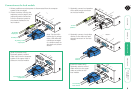
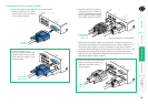
Link to remote
module
6 [Dual VGA variant only]
Optionally attach a serial
connection lead to the female
connector on the local module
and attach the other end to
a vacant serial port on your
computer.
5 Attach the connector of the
category 5, 5e or 6 link cable (up
to 50 metres in length) to the
‘TO REMOTE’ socket on the local
module (labelled ‘LINK 1’ on dual
VGA variants).
SRX
TO
REMO
TE
LINK
PO
WE
R
ON
®
OUT
A
B
[Dual VGA variant only] Attach
the connector of a second
category 5, 5e or 6 link cable
(up to 50 metres in length) to
the ‘LINK 2’ socket on the local
module.
Secondary link to
remote module
LOCAL
®
IN
A B
IN
OUT
SR
X
TO
R
EM
O
T
E
LI
N
K
PO
W
ER
O
N
®
5500
OU
T
LIN
K
O
REMO
TE
ON
To computer
serial port
To optional
power supply
Low power
indicator
connector of the optional power
supply to the ‘POWER’ socket of
the local module.
2 Attach the IEC power lead to the
power supply body and insert the
mains plug of the lead to a
nearby power outlet.
Note: If a power adapter is
plugged into the module but
not switched on, it will prevent
the unit from deriving power
from the USB connection.