


Chapter 3: Installation
724-746-5500 | blackbox.com
Page 19
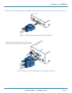
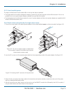
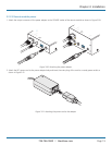
3.2.2.5 Remote module power
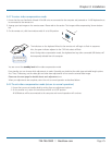
1 Attach the output connector of the power adapter to the ‘POWER’ socket of the remote module as shown in Figure 3-20:
LINK
POWER
OUT
TOLOCAL
ON
Wiza rd VGA/US B
V M
E X T E N D E R
Figure 3-20. Attaching the power adapter
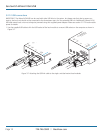
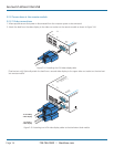
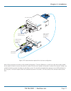
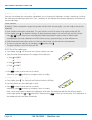
2 Attach the IEC power cord to the power adapter body and insert the mains plug of the cord to a nearby power outlet as
shown in Figure 3-21:
Figure 3-21. Attaching the power cord to the adapter
LINK
POWER
OUT
TOLOCAL
ON
Se rv Swi tc h Wizard VGA/ USB
™
B L A C K
B O X K V M
E X T E N D E R