


Chapter 3: Installation
724-746-5500 | blackbox.com
Page 25
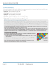
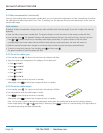
This flash sequence
indicates that you
are at Standby level
Num
Lock
Caps
Lock
Scroll
Lock
The indicators on the keyboard linked to the remote unit will begin to flash in sequence.
Also, the green indicator adjacent to the CATx link socket will flash.
Note: During video compensation mode, the keyboard and any other connected USB devices will
be temporarily isolated from the computer.
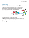
1
ON
2
You are now at the standby level within video compensation mode.
From standby, you can choose which adjustments to make. Generally you should set the cable type and cable length options
first. Then, if necessary, use the video gain and color skew adjustments to fine tune the remote video image.
Please see the next page for details about each adjustment >>>
When your adjustments are complete, return the unit to normal operation as described below:
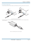
3.4.2 To exit video compensation mode (return to normal operation)
1 Ensure that you are at standby level by exiting from any adjustment options.
2 On the remote unit, return the miniature switch 1 to its OFF position.
All USB devices will be reconnected to the computer and normal operation will continue.
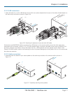
3.4.1 To enter video compensation mode
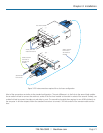
1 Ensure that the two ServSwitch Wizard VGA-USB units are connected to the computer and powered on. A USB keyboard must
be connected to the remote unit.
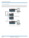
2 Arrange your test images on the remote screen. Please refer to the section ‘Test images while compensating’ shown bottom
left.
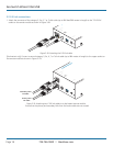
3 On the remote unit, click the miniature switch 1 to its ON position.