


Chapter 3: Installation
724-746-5500 | blackbox.com
Page 9
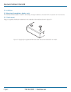
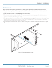
3.1.2 Rack mount
Note: The module switches are not accessible once it is inserted into the rack, therefore, check all settings before insertion.
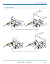
1 Place the rack securing plate (available as a separate kit) onto the front of the module and secure it with the two countersunk
screws.
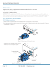
2 Orient the module on its side so that its labeled face is the correct way up.
3 Slide the module into the required rack position. The rectangular cut-out in the front upper lip of the rack allows the two
screws on the module’s upper edge to slide through.
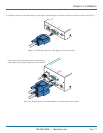
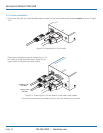
4 The rack mount chassis has a series of holes in its floor that are spaced to accommodate the two screws on the module’s lower
edge. Ensure that the screws correctly locate into the two holes of the chosen slot. The rack securing plate on the module
should now be flush with the front of the rack mount chassis.
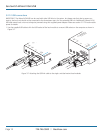
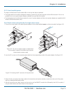
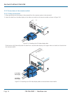
5 Use the third (pan-head) screw, in the top hole of the rack securing plate to fasten the module to the rack as shown in Figure
3-2:
Figure 3-2. Fixing the module into the rack
1
ON
4
2
3
LINK
LOCAL
POWER
OUT
IN
IN
TOREMOTE
ON
Se rv S wi tch Wi zard VGA /US B
™
B L A C K
B O X K V M
E X T E N D E R