


724-746-5500 | blackbox.com
Page 32
724-746-5500 | blackbox.com
Chapter 2: Installation
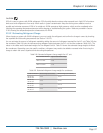
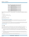
Vertical runs are based on a total rise of 30 equivalent feet. For longer rises, make individual calculations. Sizes assume the use of
single risers; double risers may be necessary.
CAUTION
Do not exceed 150-foot maximum liquid line length.
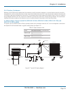
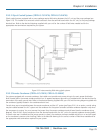
If the condenser is installed above the evaporator, the discharge line should include a p-trap at the lowest point in the piping. The
highest point in the discharge line should be above the condenser coil and should include an inverted trap to help prevent oil and
liquid from flooding back to the compressor during off cycles.
If the condenser is installed below the evaporator, an inverted trap the height of the evaporator coil is required on the liquid line
to help prevent oil and liquid from flooding back to the compressor during off cycles.
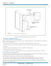
2.8.3 Condensate Drain Line
A condensate pump is factory installed. The drain line connection is typically a
1
⁄2” FPT fitting. The installer must connect a drain
line (customer supplied) to the drain fitting to remove water from the cabinet.
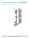
Access the condensate drain fitting through the top or bottom of the cabinet as configured with the water/glycol or refrigerant
piping connections. Access the drain fitting from outside the cabinet on top-piped units. Access the drain fitting inside the cabinet
behind the front discharge panel on bottom-piped units. An entrance hole for the drain line is provided in the floor of the fan
compartment. See the installation drawing provided with your unit for the location of the condensate drain fitting.
Connect the drain line to the fitting and direct the water to an appropriate place, such as an open building drain with an air gap,
per local and national plumbing codes. After the piping is installed, seal the gap between the drain line and the cabinet entrance
hole so air won’t leak.
CAUTION
Do not use chloride-based water-conditioning additives in the condensate drain pans. This will cause corrosion on the coil fins.
2.9 Utility Connections
2.9.1 Main Power
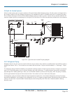
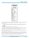
The Cold Row is available in single- or three-phase variations and a wide range of voltages. Examine the unit nameplate to
determine the operating voltage, frequency, and phase of the system (see Figure 2-12). The nameplate also provides the full load
amps (FLA), the current the unit will draw under full design load, the minimum circuit ampacity (MCA) for wire sizing, and the
maximum fuse or heating, air conditioning, refrigeration (HACR) breaker size (MAX FUSE/CKT BKR) for circuit protection. The
unit’s nameplate is located inside the cabinet within the electrical box.
NOTE: If the nameplate states MAX FUSE/CKT BKR, it is required to use fuses or a HACR-type circuit breaker to protect the
system. Other protection devices are not allowed based upon the product listing.