


724-746-5500 | blackbox.com
Page 40
724-746-5500 | blackbox.com
Chapter 2: Installation
3. Referring to Chapter 3, start the A/C system and use the system controller to lower the room temperature setpoint 3–5° F
below actual room temperature to ensure that cooling remains on as the unit is charged.
When fine tuning the charge on cool days, it may be necessary to restrict the airflow across the condenser coil to raise the pres-
sure. The fan closest to the header must be running. When fine tuning the charge, ensure the pressures are correct for the type
of refrigerant used. Refer to the tables in Section 2.10.3 for the operating temperature and pressure ranges for R410A refrigerant.
4. Block off a portion of the intake air to the condenser until a constant discharge pressure can be obtained. This will lower the
possibility of overcharging. Allow the discharge pressure to rise to 445–480 psig and hold it constant.
5. Slowly meter liquid refrigerant through the suction side while watching the pressure gauges and monitoring superheat and
sub-cooling temperatures.
CAUTION
Add liquid refrigerant slowly to prevent the refrigerant oil from “washing out” of the compressor.
6. Take a superheat temperature reading near the feeler bulb from the auxiliary control module with the temperature measuring
device well insulated. The ideal superheat temperature is 12–15° F. Maximum allowable superheat temperature is 20° F.
CAUTION
Do not exceed 20° F superheat. Exceeding this temperature may cause failure of the compressor.
7. While monitoring the pressure, take a sub-cooling temperature reading on the output side of the condenser. The sub-cooling
temperature should be 10–20° F.
8. If necessary, (slowly) add liquid refrigerant to the suction side to achieve the correct sub-cooling temperature.
CAUTION
Remove the blockage from the air intake of the condenser.
9. Fill out the applicable sections of the Warranty Registration and Start-Up Checklist.
2.10.2.4 -30° F Ambient Applications
NOTE: For units designed for -30° F operation, a receiver is used to store the refrigerant during the time the condenser is not
using the extra refrigerant charge.
1. Follow Steps 1–8 in Section 2.10.2.3. Once superheat and sub-cooling temperatures are stabilized, add more refrigerant to the
receiver.
NOTE: Do not exceed 80% of the total condenser and receiver volume to allow room for expansion.
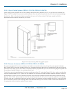
2. A refrigerant level sight glass is located on the side of the receiver to assist the service technician in charging the
air-conditioning system. Determine the proper charge by viewing the level of refrigerant in the receiver while the unit is running
at an elevated discharge pressure.
3. Keep the air intake to the condenser blocked and maintain the discharge pressure at 445 psig and hold it constant. The
condenser fan nearest the condenser header should be operating continuously. All other fans, if additional fans exist, should be
off during this time.
4. Add additional refrigerant charge to the receiver as needed until the refrigerant level rises to the center of the sight glass,
indicating that the receiver is 80% filled.
When the refrigerant in the receiver reaches the sight glass, the unit is fully charged.
CAUTION
Remove the blockage to the air intake of the condenser.
5. Fill out the applicable sections of the Warranty Registration and Start-Up Checklist.